Recent Posts

Pages: 1 2 3 [4] 5 6 ... 10
31
Transformer calculator (Public) / Re: Links to calculation pages
« Last post by Bob on February 12, 2013, 06:53:19 AM »
Silvio,
    do you have the transformer calculator in 64 bit? 
32
Transformer calculator (Public) / Re: Links to calculation pages
« Last post by Bob on February 12, 2013, 06:51:21 AM »
silvio, where can you buy the lamination iron to make the cores for a transformer?
33
Transformer calculator (Public) / Links to calculation pages
« Last post by Silvio Klaic on February 02, 2013, 02:07:39 PM »
Here is the list of other useful pages with information on transformer calculation which I collected over the years.
So if you want go in depth looking in calculations, try with these ones:

General
http://www.youtube.com/watch?v=a4pxpG83LUY
http://en.wikipedia.org/wiki/Transformer_types
http://en.wikipedia.org/wiki/Transformer
http://en.wikipedia.org/wiki/Magnetic_core
http://www.smps.us/magnetics.html
http://www.allaboutcircuits.com/vol_2/chpt_9/7.html
http://info.ee.surrey.ac.uk/Workshop/advice/coils/terms.html

Laminated-iron core
http://sound.westhost.com/xfmr.htm
http://www.valveheart-bg.com/theory/transformer.html
http://openbookproject.net/electricCircuits/AC/AC_9.html
http://en.wikibooks.org/wiki/Electronics/Transformer_Design
http://hyperphysics.phy-astr.gsu.edu/Hbase/magnetic/transf.html
http://hyperphysics.phy-astr.gsu.edu/Hbase/magnetic/tracir2.html
http://www.giangrandi.ch/electronics/trafo/trafo.shtml
http://scialert.net/fulltext/?doi=ajsr.2013.122.128&org=11
http://ntrs.nasa.gov/archive/nasa/casi.ntrs.nasa.gov/19660001049_1966001049.pdf
http://www.epanorama.net/documents/components/transformers.html

Ferrite ceramic core
http://www.bcae1.com/trnsfrmr.htm
http://www.66pacific.com/calculators/toroid_calc.aspx
http://users.catchnet.com.au/~rjandusimports/index.html
http://www.mag-inc.com/design/design-guides
http://www.poweresim.com/Xformer/Select_Application_Front_Page.jsp
http://www.epcos.com/web/generator/Web/Sections/DesignSupport/Tools/Ferrites/Page,locale=en.html
http://schmidt-walter.eit.h-da.de/smps_e/smps_e.html
http://www.lodestonepacific.com/distrib/pdfs/Magnetics/Design_Application_Notes.pdf
http://www.actown.com/download/Catalog/Oem_Design_Guide.pdf

Air core
http://colomar.com/Shavano/inductor_info.html
http://hamwaves.com/antennas/inductance.html
34
Other (Public) / Solar cells test (from calculators)
« Last post by Silvio Klaic on January 27, 2013, 02:11:52 AM »
During years I collected several solar cells from malfunction calculators and now I'm thinking to combine and use them to make solar charger for single AA or AAA NiMh batteries.
I have two AM-1417 and one SA-3515 cells from Sanyo, one unknown marked KSC08B and 3 newish HP-3012DS.
Only data that I was able to find are for AM and HP cells: at 200 lux they produce 1.5V and 5-20 uA.
Now 200 lux is common lighting at desk level from indoor light source, but I planning to use them outside where light levels are 10 to 1000 times greater.

For charging NiMh battery, produced voltage of 1.5V is sufficient, but the question is whether these cells can produce enough power for reasonably fast charging. My term of reasonably fast charging is up to 8 sunlight hours to charge single AA 2500 mAh battery.
That is constant current of at least 312 mA per hour.

Test preparation

As you can see on image above old cells was electrically connected with conductive tape, which I didn't have. So I connected it with conductive glue. Process is simple; place wires and hold it fixed with some type (top center on image).
Then apply 2-3 thin layers of conductive glue in 20-30 min interval (bottom center on image). After 12 hours of drying apply hot glue on top of wires to fixate and isolate them (top right).
After cleaning up excessive glue, all is set to do testing (bottom right).

Test setup and testing
I was using 22W fluorescent lamp on mechanical arm as light source. With this I was able to precisely adjust height to testing surface. I measure wanted luminosity with lux meter LX-101.
Testing cell was done by connected it to voltmeter and precise trimmer potentiometer in parallel with voltmeter. Then I adjust trimmer to get exactly 1.5V and disconnect cell to measure resistance of trimmer. Measured resistance is then compensated for voltmeter impedance and by ohms law calculated to current at that luminosity level.
Description of my precise trimmer potentiometer which I use in this measuring can be found here.

Results
102550751002505007501k2.5k5k7.5k10kLux
SA-3515-40,000,722,263,815,1713,6527,4742,2856,12143,55285,32411,11488,75uA
AM-14170,261,463,014,445,9915,1829,6844,5359,67155,11304,41446,58539,72uA
KSC08B-9810,000,441,492,413,519,4619,1129,8539,73105,93211,42317,27411,11uA
HP-3012DS0,391,202,203,104,048,6214,4519,7824,1944,6666,5283,6294,49uA
As you can see from test results, data given from datasheet matches my results. However I notice some difference, mainly between two AM-1417 cells. Second cell (not shown in table) have almost identical response as SA-3515 cell.
This means that older cells have bigger differences than new ones. Not sure if this is to fact that they are used more or/and aging influences.

You may notice that new cells (HP-3012) have better sensitivity at lower light levels, but are weaker at high luminosity. Which is shame because technology of solar cells is much improved? Or there is some other reason for making these bad cells...
I was measure up to 10k lux which is max for my 22W fluorescent lamp. 10k lux is luminosity outside at cloudy day and on sunny day without clouds can reach over 100k lux.

To compare efficiency of these cells to standard outdoor solar panels, this data need to be converted to standard test irradiance (normally at 1000W/m2).
I don't have data how exactly my fluorescent lamp have luminous efficacy, so I assume to be about 70 lux/W, with this irradiance of 7 klux is 100W/m2. To convert data, I'm dividing lux measurements points with 70 to get W/m2.
As you can see from graph current is almost linear and I presume that test at 75 klux will give about 10 times more current than on 7.5 klux.
So using max readings of 10 klux and multiplying calculated power with 7 will get me approximately results for irradiance of 1kW/m2.
Then dividing these results with surface is close enough data for comparing power per cm2 with standard solar panels.
Cells/panelsdimensionSurfacePower per surface @ Irradiance 1 kW/m2
SA-3515-415,5x35mm5,425cm20,946mW/cm2
AM-141714x35mm4,9cm21,157mW/cm2
KSC08B-98111,5x30mm3,45cm21,251mW/cm2
HP-3012DS9,5x29,5mm2,8025cm20,354mW/cm2
SES 440J655x537mm3517,35cm211,372mW/cm2
Sole SL-40P669x500mm3345cm211,958mW/cm2
SEM-45W-M670x540mm3618cm212,438mW/cm2
SEM-180W-M1580x808mm12766,4cm214,100mW/cm2
In this table I compared result with some standard solar panels.

Conclusion
Anyhow, making charger from 7 cells which I have is not good idea. These cells are too weak, about 10 times worse compared to standard solar panels at same surface levels.
To build charger I'll need to have 100 times more of these cells. There is no way I could find that amount old cells and with new I'll need minimum 500 of them.
Calculation for charging single AA NiMh 2.5 Ah battery at 1.5V with irradiance at 1kW/m2:
1922 cells of HP-3012DS: 5386.4 cm2, 1.272 A/h = 1.907 W/h, 1.967 hours.
For same price solar panel Maxcell 40 Poly: 3345cm2, 3.555A/h = 5.33W/h, 33.8 minutes.

So these cells are no go.
I'll use them as light sensors instead LDR in my project for tracking sun movement across sky.
Another good use is irradiance meter, however I need to find precise and know light source to calibrate meter. The best I can think of it now is summer sun at noon without clouds, but this is only calibration for range above 100W/m2.
If you know other method for calibrating irradiance meter, let me know.

I'll conduct further testing in summer to confirm these calculations.
Another testing at that time would be with standard solar panels.
I found that they work only at high luminosity (no, indoor lighting can't be used for power source).
Another test is efficiency at different angles and with solar tracker.
There is also thermal test to see if they really lose power during higher temperatures.
35
Transformer calculator (Public) / Re: TO DO list
« Last post by Silvio Klaic on January 26, 2013, 11:49:00 PM »
Update news
I'm working for some time now on new transformer calculator.
Currently I do tests on different calculations for different coils, mainly ferrite ones at wide frequency range.
In next month or so I'll post result of testing and future updates on program.

Program will be under GPL license and open sourced.
I'm planning to create it as dynamic HTML using java script, this way can be run on any platform, either online or offline.
I am planning to put first beta release in March.
36
Transformer calculator (Public) / Re: TO DO list
« Last post by ferahfeza on January 22, 2013, 03:47:44 PM »
Hi Silvio,
Will you release 64bit version of this program?
Thank you for great job.
Best regards.
38
Alternative / Alternative and essential links
« Last post by Silvio Klaic on February 25, 2012, 01:32:11 PM »
Now and then people ask me for links to other pages for alternative information.
So I decide to place here list of links which I find useful and I hope that this helps.

Essential:
https://www.youtube.com/user/DismantleTheMatrix
https://www.facebook.com/DismantleTheMatrix
http://freemantv.com
http://www.andrewbartzis.com
https://www.youtube.com/watch?v=ioGxyeyuHco
http://www.askteal.com
http://www.universaltruthschool.com
http://www.youtube.com/watch?v=127BR5b8Hm4
http://whatonearthishappening.com/
http://www.youtube.com/user/WhatOnEarth93
http://www.kybalion.org/kybalion.php
http://theresonanceproject.org
http://www.youtube.com/user/Electrobadgr
http://www.youtube.com/user/FREEDOMCENTRAL
http://www.youtube.com/user/KelliInTheRaw
http://pharmacistben.com
http://thomassheridanarts.com
http://www.youtube.com/user/ThomasSheridanArts
http://georgekavassilas.org
http://www.our-journey-home.com
http://www.youtube.com/user/spiritualessence
http://www.youtube.com/results?search_query=allfaaraa
http://universaltruthschool.com
http://www.youtube.com/user/MrAstrotheology
http://www.jordanmaxwell.com
http://www.davidicke.com
http://www.youtube.com/user/davidicke
http://www.unitethecollective.com
http://www.youtube.com/user/dero7
http://www.awakening.2freedom.com
http://www.youtube.com/user/AwakanedBeingness
http://manithyasudevi.blogspot.com
http://www.youtube.com/user/MaNithyaSudevi
https://lifeblissprograms.org/e-downloads
https://lifeblissprograms.org/e-books/flip-books/ga44why_meditation_3rd_edn_2011/index.html
http://www.youtube.com/user/LifeBlissFoundation
http://ascension101.com/en/ascension-tools/33-ascension-tools/105-fear-processing-exercise.html
http://www.bashar.org
http://www.abraham-hicks.com
http://www.lawoftime.org/thirteenmoon.html
http://www.hiddenmeanings.com
http://www.youtube.com/user/bdona4556
http://www.feandft.com
http://www.youtube.com/user/PathToAscention
http://www.bluestarprophecy.com
http://sacredscribesangelnumbers.blogspot.com/p/index-numbers.html

Important/other:
https://www.youtube.com/user/RedPillR3volution
http://meria.net
http://loveovermind.wordpress.com
http://thetruthergirls.com
http://emesowum.com/kt/interviews/
http://www.youtube.com/user/GreenGuerrillas
http://www.starknowledgeconference.com
http://www.youtube.com/user/lisamharrison
http://www.lisamharrison.com
http://www.youtube.com/watch?v=MhKVElO8JGo
http://gnosticteachings.org
http://www.youtube.com/user/TruthNeverTold
http://projectavalon.net
http://www.youtube.com/user/AlphaZebra
http://www.youtube.com/user/jonwhat2003
http://healingartscommunitycenter.com
https://www.youtube.com/user/CrystalStarseed444
http://www.ascension-pioneers.com
http://www.youtube.com/user/ASCENSIONPIONEERS
http://www.youtube.com/user/DanielTheDorian
http://www.youtube.com/user/jonwhat2003
http://www.youtube.com/user/herbgardner00
http://www.thebookofaquarius.com
http://danielofdoria.com
http://www.youtube.com/danielofdoria02
http://devinemiracles.com
http://www.youtube.com/user/DevineMiracles
http://www.cosmicgaia2012.com
http://www.quantumk.co.uk/quantumk_video.htm
39
Other (Public) / Re: Low cost tweezers type LCR meter
« Last post by Silvio Klaic on November 07, 2011, 10:39:31 AM »
Progress so far:
1. SMD probe
For my tweezers I need some SMD probes.
At first I was planning to buy one, but pricing are too high for my taste.
So I search for alternatives on net and I find this:

I’m also planning to modify this, because for around 1MHz I need shielded probes.
Therefore I plan to use only wire in middle and GND all around.

2. Protection from charged capacitors
Almost all measurement tools for capacitors have warning not to connect charged capacitor.
My LCR tweezers have the same problem, so to solve it I decide to place something between probes to shorten them.
Then if I grab charged capacitor with probes, it will be discharged.
To perform measurement I plan using switch to signal device for breaking short point and begin measurement.
With that, tweezers will be protected from discharging current and consume less power, because it will do measuring only when button is pressed.

Big problem is what to use. Obviously choice will be relay, however they are all big.
Smaller ones are reed relays but they can sustain only small currents.
Another problem with relays is that they consume a loot of power during operation.
Using MOSFET is better solution however for this I need at least 10V for gate.
That means adding voltage doublers or more. Another problem is that this protection doesn’t work when device is powered off.
So on end I decide to use switch for shortening/breaking probes and signaling device to begin measurement.

3. Digitally selected wide range of resistors
Now, what I really need is not simple 6 point selector for predefined 6 resistors like in standard DMMs.
Main problem for accurate testing resistors in voltage divider setup is to get proper resistor pair for targeted output voltage.
In measuring capacitance and inductance this isn’t that significant because I can change frequency and match reactance to used resistor.
Ideal digital potentiometer for my need would be one with range from 0 to 10Mohm in resolution of 1 ohm.
Simply put, to achieve this I’ll need 10 million combinations and this can be done with 24 bit – at least 24 resistors + switches to get from 0 to 16777215 ohms in 1 ohm resolution.
This solution of 24 bits is too big and using single chip digital potentiometers have other problems.

Biggest digital potentiometer what I found have 1Mhom (AD5241BRZ1M) in 8bit increment.
That means increment of about 3.9 kohms. But I’ll need 10 of them in series to get 10Mohms.
Fine tuning to increment of 0.39ohms can be done by putting another two of 10kohm and 100 ohm in series, however big issue is frequency bandwidth which is limited to 6 kHz.
So for my purpose digital potentiometers are not good enough.

3.1. Digital selector (shift register, microprocessor?)
So I have to do it with switches and resistors.
When it comes to selecting it is big question how to do it.
Shift register is my first choice but having lot resistors to select means calculations for them how to select it.
Now my microcontroller for this purpose must already calculate guessed value for resistor, then find/calculate closest one available from list which contains calibrated values for each resistor and then set it up.
These calculations require a loot of memory, especially for storing calibrated values.
Another microcontroller can be handy, with extra memory designated to serve only for resistors.
I find out that price between shift registers and microcontrollers are almost identical, so I chose to go with another microcontroller as replacement for shift register.

There are some other advantages in using microcontroller; mainly entire device becomes modular with two separated programming.
Another one is that main microcontroller no longer stores detailed data for each resistor and don’t have to calculate for them.
Basically my idea is; when it calculate guessed resistor, it will send that value to second microcontroller.
That one would find/calculate closest resistance for measure and return that value + set up resistors to that value.

For numerous reasons which I wouldn’t discuss here I decide to go with Microchip PICs microcontrollers.
For my needs I require 16 pins for selecting resistors thru switches (see 3.3. for number) + 3 for SPI serial communication between main microcontroller/PC and this one.
This is total of 19 pins, so suitable PIC with at least 19 I/O and Serial Communication module are PIC16F1516 and PIC24F16KA102 series.
I deicide to go with PIC24 series and main reason is speed – faster calculations, even this series is double the price of PIC16 series.

3.2. Analog switchers or Reed relays?
Now about switches; the best would be to use reed relays but this can take up much of space and most important one: consume significant amount of current in operation.
So I discard them as solution.
Analog switches are worst solution especially if used in series, but there are now available better switches than old CD4066.
I find that FSA2267 with 0.35 ohm on resistance and 45 MHz bandwidth is far better solution.
So I chose to use this switches instead.

3.3. Chosen set of resistors for optimal resistor range
This was tough one and I spend a loot of time on this.
First there was problem of deciding what setup to use; resistors in series or parallel configuration.
There are advantages and disadvantages to both.

Parallel combination provides easier calibration and reduction in errors by division - to some degree.
A problem with this is non linear result due division and calculations for selected resistor must be performed in floating point math, which is problematic with microcontroller.

When using resistors in series like ladder, analog switches are adding up their resistance resulting bigger error and problematic calibration.
On other hand result is linear and easy to calculate/set.
So even I decide at first to go with parallel combination, low resolution vs. number of resistors at higher resistance range was too great to be satisfactory.
At end I decide to go with series setup.

Obviously 24 resistors are too much and 6 are minimum.
Usually minimal set of resistors to cover entire range would be 200, 800, 9k, 90k, 900M and 9M ohms – 6 bits to cover.
Now the question is why using these exponential values?
What is optimal resolution and accuracy?
To answer these questions, I make this graph:
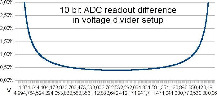

Here is shown difference between two values at different ADC readout points.
10 bit ADC can distinguish about 4.89mV.
So in ideal environment using 1k for testing another 1k resistor, ADC readout will be 2.5024437928V or 2.4975562072V.
After calculation we get 1001.9569471624 or 998.046875 ohms.
In both results, difference or error from real value is 0.1953125%.

As can be seen on graph, this small error is only at mid point.
Going to any edge (bigger resistor difference) produces larger error.
Note that this error is identical for any voltage. So targeting half of input voltage will get the best possible result.
To reduce this error, 12bit ADC will be better solution, which I plan to use.
My soundcard have already 16bit ADC so designing for 12bit ADC will be better solution.

To get best resolution and accuracy is to have only ADC error.
In 10 bit ADC resolution for 100 ohm is 0.1953125 ohm, for 1 kohm 1.953125 ohm up to 10 Mohm and 19531.25 ohm resolution.
Using 10 kohm resolutions at 10 Mohm measuring range is waste, because it doesn’t affect reading at ADC.
However at 12 bit ADC this would have big difference, because minimal resolution for 10 Mohm is 4882.8125 ohms.

So from this math by rounding values of 12 bit ADC, I got these resolutions:
Resistor rangeresolutionx100x1000
1-100.00050.050.5
10-1000.0050.55
100-1k0.05550
1k-10k0.550500
10k-100k55005k
100k-1M505k50k
1M-10M50050k500k
Lowest safe resistor is 200 ohms (16.5mA at 3.3V) and best resolution at 200 ohm is 0.1 ohm (rounded).
Starting from here including possible errors and number of switches I decide to start with resolution of 1 ohm.
In range from 200 ohms to 10 kohms in resolution of 1 ohm, resistor in series must be: 1, 2, 4, 8, 16, 32, 64, 128, 256, 512, 1024, 2048, 4096 and 8192 ohms.

This is 14 bits or 14 switches with these resistors to make that range and it’s obviously already too much.
If best resolution is multiplied by 100, errors in reading will increase by 0.000061% and will not cross 0.2% error of 10 bit ADC, which is acceptable.
For this, new resistor series in range 200 to 1 kohm would be: 10, 20, 40, 80, 160, 320 and 640 ohms with resolution of 10 ohms.
For 1k to 10k range 50 ohm resolution is needed and we use previous resistors to continue into this series: 800, 1600, 3200 and 6400 ohms.
So far 10 bits and to complete series to 10 Mohms another 12 bits are needed which is in total too much.

If resolution was increased by 1000 times, this will increase error by 0.00406% and become 0.101688021% well below 0.2% error.
Series for this resolution will be: 100, 200, 400, 800, 1k, 2k, 4k, 8k, 10k, 20k, 40k, 80k, 100k, 200k, 400k, 800k, 1M, 2M, 4M and 8M ohms.
Total of 20 bits, but this series can be optimized further, if lower resistances are combined together they form enough value to eliminate next bigger resistor.
100+200+400+800=1500 ohms which covers 1k range and with resolution in 1k-10k range of 500 ohms this fits perfectly next in line to 2k. So 1k resistor can be eliminated.
Optimization method will also eliminate others too; 10k, 100k and 1M ohm.

Now, this form series of 16 bits/switches and this is first case below 20bits which I find acceptable.
Maximal errors in reading/calculating when using combination of these resistors in 200 to 10 Mohm range for 12bit ADC is 0.102% and for 10bit ADC 0.4064%.

After simulating with new setup and 12bit ADC I got these results:
Resistor rangeMax resolutionReal resolutionError10bit ADC rez. 10bit ADC error
0.1-0.2Ω0.00050.0243719.895%0.0956995.695%
0.2-1Ω0.00050.0245911.113%0.0984133.324%
1-10Ω0.00050.02712.427%0.10769.129%
10-100Ω0.0050.058270.263%0.219231.057%
100Ω-1kΩ0.050.532920.053%1.946870.217%
1kΩ-10kΩ0.55.329260.049%19.468750.196%
10kΩ-100kΩ553.466790.049%194.68750.196%
100kΩ-1MΩ50534.91210.049%1946.8750.196%
1MΩ-10MΩ5005351.97850.049%19468.750.196%
10MΩ-30MΩ500015815.696020.053%63995.714280.213%
30MΩ-100MΩ5000103962.02530.104%413097.826070.416%
Max resolution colon is used to set up maximal resolution for 12bit ADC.
Real resolution colon contains simulated values of actual resolution.
As can be seen in error colon, errors from simulated/measured/calculated values do not go to maximal error of 0.102% and this is because combination of resistors from lover range actually adds better resolution in higher range.
To be precisely they add about 50% better resolution, which is seen as about 50% better readout.
For comparison I calculate/simulate resolution and errors for 10 bit ADC.
This shows that is possible to make decent measurement with it too, but price difference is so small and this is measure equipment after all.

Conclusion
With this setup I got far better results in simulation for measuring resistance.
There is slightly higher resolution and lower errors than in original setup.
Capacitance and inductance didn’t change much, only slightly at edges of measuring range.

Basically when using this detailed resistor ladder accurate measuring reactance can be done with only two frequencies.
In main measurement range there is frequency around 1.1 kHz for capacitors and 2.3 kHz for inductance – frequency are for targeted point of half input voltage.
Higher frequencies are needed only for measure lower ranges; for inductors less than 30mH to increase reactance and in capacitors less than 15pF for decrease reactance.
Lower frequency is needed for higher values; more of 700H in inductance to decrease and above 1uF for increase reactance in capacitor.

This also adds to justification of usage 16 resistors for digital potentiometer, especially if experimental PC version shows that square wave AC is far worst for measure than sine.
PWM module can generate almost sine wave in this small frequency range.

4. Power supply from battery – in this case parallel PC port
With all above I practically have finish setup for analog part of my PC/LCR tweezers device.
As I mention already I plan to use 3.3V power supply.
Source in PC version would be 5V from LPT port output pins, and in tweezers from dual NiMH 2.4V/300mA batteries (4.8V).
For stable 3.3V regulator I plan to use S-1132B33 LDO Regulator with shutdown pin.
For PC version I also need voltage level translator to enable normal communication between 5V LPT port and 3.3V MCU.
40
Other (Public) / Re: Low cost tweezers type LCR meter
« Last post by Silvio Klaic on October 30, 2011, 10:47:51 AM »
After doing some research and simulations, here is update by key points:

1. Cheap digitally controllable frequency generator in range of 100 Hz up to 2 MHz
After some research and thinking I decide to use clock pulse (square wave) from microcontroller as AC signal, generated by PWM module.
Using DDS is too expensive. Replacement can be made by using monolithic function generator like XR-2206.
Of course controlling frequency can be difficult.
By using 8 or more analog switches + shift register with different resistors at each output and joined at pin 7 or 8 of XR2206 in parallel, it is possible to get frequency control to some degree.
How detail it would be, depends on resistors in parallel combination.
Generated signal will have unknown frequency, so it must be measured at microcontroller, which bring additional complication.

When it comes to basic, it is totally irrelevant what type of signal is used. Wave type is only important for calculating exact values for DUT.
So by using square wave instead sine wave, I will need to calculate several first odd harmonics to get enough precise value of DUT.
That calculation is performed only once at end of all measurements, so it’s not time critical.

2. Digitally fast selectable resistance for range.
In this segment I did some extensive simulations.
After looking schematics of classical DMM and thinking, I decide to go with resistor in parallel combination rather than series.
Here is some schematic and links that I find useful:

First thing I was doing are simulations to see what resistors I need for selection.
I used at first standard set of 6 resistors; 100, 1k, 10k, 100k, 1M and 10M ohms.
However there was a problem, microcontroller can provide current of max 20mA, which means that I can’t use 100 ohm resistor.
First closest resistor for 5V supply with safe side of about 15mA is 330 ohms.

With this basic resistor set in place there is mater of frequency.
And after some thinking I decide not to make experimental version on microcontroller, but on PC similar to ZRLC meter.
With this I will have far better experiment environment to test different frequencies and wave shapes.
After I finish PC version I’ll have completed half of LCR meter, because PC with soundcard replaces only microcontroller and display.

So for simulating I use frequencies from 100 Hz to 22050 Hz, which classical 16bit soundcard can generate.
DUT detection is made by applying at lowest resistance low and hi frequency.
If voltage is identical on both readings and it is 0 or Vin, then test is repeated using highest resistance with low and hi frequency.
First reading non 0/Vin and closest to half of Vin is used to decide what type of DUT is.
According to that, it is calculated guessed value for DUT.

Here I got problem, I need to choose resistor and frequency to be the best for accurate measurement.
At first tests I use loop and go thru available resistors calculating frequency for each one and using only one with highest frequency.
This method produced strange readings with error difference of few percent at two closes DUT values.
After that I was made full frequency analysis to see what is going on.
Here is a result for capacitor calculations:

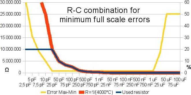
Blue line shows used resistors which have at least error difference (yellow line) in full frequency (100-22050Hz) scale.
Simply put if this resistor is used with any frequency it will produce lowest calculation errors than any other.
For analysis to get best accuracy I was using only resistors with error difference below 2% and in that region I see that graph is hyperbola.
After calculations I came to this formula:
Rmeasure=1/(4000*Cguessed)

So with this formula I can from guessed capacitor get the best resistor for measure (red line).
After that, there was left a problem to get right frequency in combination with that resistor to obtain the best measurement.
Then I was made another calculations with this result:

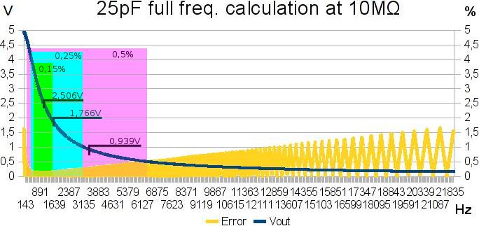
This graph shows full frequency calculations for 25pF capacitor with 10Mohms resistor.
Calculations for other capacitors are also done with similar results.
As you can see, error (yellow line) between real value and simulated reading do not pass 2% for entire frequency range.
To get the best frequency for testing we must target midpoint at certain frequency band.
Using filter for 0.5%, 0.25% and 0.15% errors I get frequency band in which is best to perform measurements.
Guessed capacitor is in most cases off the real value, so using bigger band of frequencies is logical choice, however by already selecting right resistor we done that.

So now it is only left to target more precise region, and using band with 0.15% error give us at midpoint 2.506V.
This is actually recommended value – half of Vin (5V in my case) for measurement in voltage divider setup.
After recalculations I get next formula for determining optimal frequency:
fmeasure= sqrt(3)/(2*pi*Cguessed*Rmeasure)

I was done similar simulation-calculations for inductors.
When it comes to selecting right resistor, result was identical as in capacitors, I only got inverted hyperbola.
So formula is slightly different:
Rmeasure= 25000*Lguessed

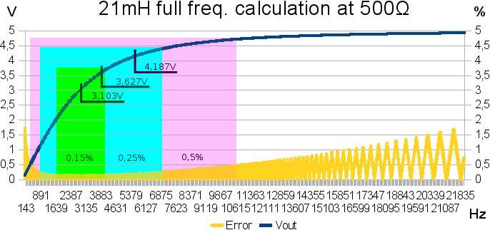
But when determining right frequency there I got much different results:

As you can see, frequency band for 0.15% error have midpoint at 3.103V.
This is not like capacitor and further tests + simulations confirmed that this is better than 2.5V.
So formula for getting right measuring frequency of inductor is:
fmeasure=Rmeasure/(2*pi*Lguessed*sqrt(1.613))

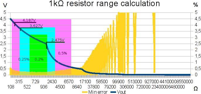
On end I made simulations for resistors, but I was using DC voltage of 5V, not AC signal.
I use this to eliminate possible inductance and capacitance of resistor – DUT.
If I want to know what inductance or capacitance resistor have, I can manually set measurement for it.

Note for graph; I used resistors in exponential increased value, so error regions and midpoint don’t match visually.
Used resistors are in this increment: ...98, 99, 100, 110, 120...
But as you can see in lowest error region I got midpoint at 2.475V which I rounded to 2.5V, because this is more convenient.
So formula for selecting right resistor is:
Rmeasure=Rguessed

After I performed these analyses and take simulations, I got far better results than with previous test methods:
Capacitor
RangeResolutionError
1pF-1nF1pF0.130%
1nF-1uF1nF0.130%
1-10uF15nF0.137%
10uF-100uF1uF0.83%
100uF-1mF10uF9.64%
1mF-2mF500uF23.35%
Inductor
RangeResolutionError
1uH1uH100.00%
2-10uH1uH22.39%
10-20uH1uH7.47%
20-30uH1uH4.78%
30-50uH1uH2.98%
50-100uH1uH2.19%
100-200uH1uH1.06%
200-500uH1uH0.52%
500uH-1mH1.5uH0.22%
1mH-1H1mH0.13%
1H-1kH1H0.13%
1-50kH250H0.52%
50-100kH1kH1.29%
100-200kH15kH5.55%
Resistor
RangeResolutionError
0.1Ω0.2Ω100.00%
0.2-1Ω0.2Ω61.29%
1-3Ω0.2Ω8.16%
3-10Ω0.2Ω4.19%
10-30Ω0.2Ω1.34%
30-100Ω0.3Ω0.55%
100-300Ω0.6Ω0.27%
300Ω-1kΩ0.21%
1-3kΩ0.26%
3-10kΩ20Ω0.35%
10-30kΩ80Ω0.26%
30-100kΩ260Ω0.33%
100-300kΩ780Ω0.26%
300kΩ-1MΩ3kΩ0.42%
1-3MΩ7.6kΩ0.25%
3-10MΩ20kΩ0.35%
10-30MΩ76kΩ0.25%
30-100MΩ580kΩ0.53%
100-300MΩ4.6MΩ1.37%
Values below 200uH and 10pF can be far more accurate by using frequency of 1 or 2MHz.
Resistors below 30 ohms will remain inaccurate because I can’t use resistor lower than 330 ohms.
However I considering using 3V supply which will enable me to go low as 200 ohms, but for this I need to do more simulation and testing.

Off course this is all done in simulator with ideal DUT, and I place limit of 10bit ADC readout.
So actual testing/measuring will be worst, because of noise and other electrical leakage.
With all of this I got required range, but I was not happy with resolution.
Solution is to add more resistors and use analog switches to combine them in parallel to get far better range and thus better resolution.

3. Accurate measuring AC voltage with ADC.
For this last point I found that precision full-wave-rectifier (precise op-amp AC to DC converter) will be best for ADC. Here are some links for that:

So to continue work on my LCR tweezers, I decide to start with PC.
With PC I can generate from soundcard precise frequency, which can be sufficient to measure almost all DUT values of required range.
In this version I will construct and test analog part of LCR tweezers:
  • SMD probe
  • Protection from charged capacitors
  • Digitally selected wide range of resistors
    • Digital selector (shift register, microprocessor?)
    • Analog switchers or Reed relays?
    • Chosen set of resistors for optimal resistor range
  • Power supply from battery – in this case parallel PC port
  • Software for selecting and working with analog part
  • Optimized programming for detecting and calculating DUT

After this, I’ll have more than half job done.
Only thing what will be left to do are integration of precise full-wave rectifier, microprocessor and display.
Pages: 1 2 3 [4] 5 6 ... 10