Show Posts

This section allows you to view all posts made by this member. Note that you can only see posts made in areas you currently have access to.


Messages - Silvio Klaic

Pages: 1 [2] 3
16
Other (Public) / Re: Low cost tweezers type LCR meter
« on: November 07, 2011, 10:39:31 AM »
Progress so far:
1. SMD probe
For my tweezers I need some SMD probes.
At first I was planning to buy one, but pricing are too high for my taste.
So I search for alternatives on net and I find this:

I’m also planning to modify this, because for around 1MHz I need shielded probes.
Therefore I plan to use only wire in middle and GND all around.

2. Protection from charged capacitors
Almost all measurement tools for capacitors have warning not to connect charged capacitor.
My LCR tweezers have the same problem, so to solve it I decide to place something between probes to shorten them.
Then if I grab charged capacitor with probes, it will be discharged.
To perform measurement I plan using switch to signal device for breaking short point and begin measurement.
With that, tweezers will be protected from discharging current and consume less power, because it will do measuring only when button is pressed.

Big problem is what to use. Obviously choice will be relay, however they are all big.
Smaller ones are reed relays but they can sustain only small currents.
Another problem with relays is that they consume a loot of power during operation.
Using MOSFET is better solution however for this I need at least 10V for gate.
That means adding voltage doublers or more. Another problem is that this protection doesn’t work when device is powered off.
So on end I decide to use switch for shortening/breaking probes and signaling device to begin measurement.

3. Digitally selected wide range of resistors
Now, what I really need is not simple 6 point selector for predefined 6 resistors like in standard DMMs.
Main problem for accurate testing resistors in voltage divider setup is to get proper resistor pair for targeted output voltage.
In measuring capacitance and inductance this isn’t that significant because I can change frequency and match reactance to used resistor.
Ideal digital potentiometer for my need would be one with range from 0 to 10Mohm in resolution of 1 ohm.
Simply put, to achieve this I’ll need 10 million combinations and this can be done with 24 bit – at least 24 resistors + switches to get from 0 to 16777215 ohms in 1 ohm resolution.
This solution of 24 bits is too big and using single chip digital potentiometers have other problems.

Biggest digital potentiometer what I found have 1Mhom (AD5241BRZ1M) in 8bit increment.
That means increment of about 3.9 kohms. But I’ll need 10 of them in series to get 10Mohms.
Fine tuning to increment of 0.39ohms can be done by putting another two of 10kohm and 100 ohm in series, however big issue is frequency bandwidth which is limited to 6 kHz.
So for my purpose digital potentiometers are not good enough.

3.1. Digital selector (shift register, microprocessor?)
So I have to do it with switches and resistors.
When it comes to selecting it is big question how to do it.
Shift register is my first choice but having lot resistors to select means calculations for them how to select it.
Now my microcontroller for this purpose must already calculate guessed value for resistor, then find/calculate closest one available from list which contains calibrated values for each resistor and then set it up.
These calculations require a loot of memory, especially for storing calibrated values.
Another microcontroller can be handy, with extra memory designated to serve only for resistors.
I find out that price between shift registers and microcontrollers are almost identical, so I chose to go with another microcontroller as replacement for shift register.

There are some other advantages in using microcontroller; mainly entire device becomes modular with two separated programming.
Another one is that main microcontroller no longer stores detailed data for each resistor and don’t have to calculate for them.
Basically my idea is; when it calculate guessed resistor, it will send that value to second microcontroller.
That one would find/calculate closest resistance for measure and return that value + set up resistors to that value.

For numerous reasons which I wouldn’t discuss here I decide to go with Microchip PICs microcontrollers.
For my needs I require 16 pins for selecting resistors thru switches (see 3.3. for number) + 3 for SPI serial communication between main microcontroller/PC and this one.
This is total of 19 pins, so suitable PIC with at least 19 I/O and Serial Communication module are PIC16F1516 and PIC24F16KA102 series.
I deicide to go with PIC24 series and main reason is speed – faster calculations, even this series is double the price of PIC16 series.

3.2. Analog switchers or Reed relays?
Now about switches; the best would be to use reed relays but this can take up much of space and most important one: consume significant amount of current in operation.
So I discard them as solution.
Analog switches are worst solution especially if used in series, but there are now available better switches than old CD4066.
I find that FSA2267 with 0.35 ohm on resistance and 45 MHz bandwidth is far better solution.
So I chose to use this switches instead.

3.3. Chosen set of resistors for optimal resistor range
This was tough one and I spend a loot of time on this.
First there was problem of deciding what setup to use; resistors in series or parallel configuration.
There are advantages and disadvantages to both.

Parallel combination provides easier calibration and reduction in errors by division - to some degree.
A problem with this is non linear result due division and calculations for selected resistor must be performed in floating point math, which is problematic with microcontroller.

When using resistors in series like ladder, analog switches are adding up their resistance resulting bigger error and problematic calibration.
On other hand result is linear and easy to calculate/set.
So even I decide at first to go with parallel combination, low resolution vs. number of resistors at higher resistance range was too great to be satisfactory.
At end I decide to go with series setup.

Obviously 24 resistors are too much and 6 are minimum.
Usually minimal set of resistors to cover entire range would be 200, 800, 9k, 90k, 900M and 9M ohms – 6 bits to cover.
Now the question is why using these exponential values?
What is optimal resolution and accuracy?
To answer these questions, I make this graph:


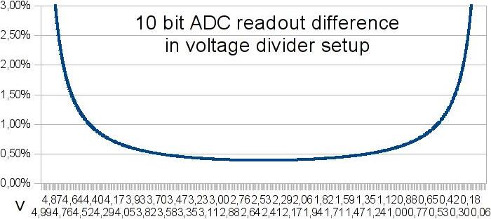
Here is shown difference between two values at different ADC readout points.
10 bit ADC can distinguish about 4.89mV.
So in ideal environment using 1k for testing another 1k resistor, ADC readout will be 2.5024437928V or 2.4975562072V.
After calculation we get 1001.9569471624 or 998.046875 ohms.
In both results, difference or error from real value is 0.1953125%.

As can be seen on graph, this small error is only at mid point.
Going to any edge (bigger resistor difference) produces larger error.
Note that this error is identical for any voltage. So targeting half of input voltage will get the best possible result.
To reduce this error, 12bit ADC will be better solution, which I plan to use.
My soundcard have already 16bit ADC so designing for 12bit ADC will be better solution.

To get best resolution and accuracy is to have only ADC error.
In 10 bit ADC resolution for 100 ohm is 0.1953125 ohm, for 1 kohm 1.953125 ohm up to 10 Mohm and 19531.25 ohm resolution.
Using 10 kohm resolutions at 10 Mohm measuring range is waste, because it doesn’t affect reading at ADC.
However at 12 bit ADC this would have big difference, because minimal resolution for 10 Mohm is 4882.8125 ohms.

So from this math by rounding values of 12 bit ADC, I got these resolutions:
Resistor rangeresolutionx100x1000
1-100.00050.050.5
10-1000.0050.55
100-1k0.05550
1k-10k0.550500
10k-100k55005k
100k-1M505k50k
1M-10M50050k500k
Lowest safe resistor is 200 ohms (16.5mA at 3.3V) and best resolution at 200 ohm is 0.1 ohm (rounded).
Starting from here including possible errors and number of switches I decide to start with resolution of 1 ohm.
In range from 200 ohms to 10 kohms in resolution of 1 ohm, resistor in series must be: 1, 2, 4, 8, 16, 32, 64, 128, 256, 512, 1024, 2048, 4096 and 8192 ohms.

This is 14 bits or 14 switches with these resistors to make that range and it’s obviously already too much.
If best resolution is multiplied by 100, errors in reading will increase by 0.000061% and will not cross 0.2% error of 10 bit ADC, which is acceptable.
For this, new resistor series in range 200 to 1 kohm would be: 10, 20, 40, 80, 160, 320 and 640 ohms with resolution of 10 ohms.
For 1k to 10k range 50 ohm resolution is needed and we use previous resistors to continue into this series: 800, 1600, 3200 and 6400 ohms.
So far 10 bits and to complete series to 10 Mohms another 12 bits are needed which is in total too much.

If resolution was increased by 1000 times, this will increase error by 0.00406% and become 0.101688021% well below 0.2% error.
Series for this resolution will be: 100, 200, 400, 800, 1k, 2k, 4k, 8k, 10k, 20k, 40k, 80k, 100k, 200k, 400k, 800k, 1M, 2M, 4M and 8M ohms.
Total of 20 bits, but this series can be optimized further, if lower resistances are combined together they form enough value to eliminate next bigger resistor.
100+200+400+800=1500 ohms which covers 1k range and with resolution in 1k-10k range of 500 ohms this fits perfectly next in line to 2k. So 1k resistor can be eliminated.
Optimization method will also eliminate others too; 10k, 100k and 1M ohm.

Now, this form series of 16 bits/switches and this is first case below 20bits which I find acceptable.
Maximal errors in reading/calculating when using combination of these resistors in 200 to 10 Mohm range for 12bit ADC is 0.102% and for 10bit ADC 0.4064%.

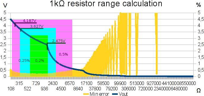
After simulating with new setup and 12bit ADC I got these results:
Resistor rangeMax resolutionReal resolutionError10bit ADC rez. 10bit ADC error
0.1-0.2Ω0.00050.0243719.895%0.0956995.695%
0.2-1Ω0.00050.0245911.113%0.0984133.324%
1-10Ω0.00050.02712.427%0.10769.129%
10-100Ω0.0050.058270.263%0.219231.057%
100Ω-1kΩ0.050.532920.053%1.946870.217%
1kΩ-10kΩ0.55.329260.049%19.468750.196%
10kΩ-100kΩ553.466790.049%194.68750.196%
100kΩ-1MΩ50534.91210.049%1946.8750.196%
1MΩ-10MΩ5005351.97850.049%19468.750.196%
10MΩ-30MΩ500015815.696020.053%63995.714280.213%
30MΩ-100MΩ5000103962.02530.104%413097.826070.416%
Max resolution colon is used to set up maximal resolution for 12bit ADC.
Real resolution colon contains simulated values of actual resolution.
As can be seen in error colon, errors from simulated/measured/calculated values do not go to maximal error of 0.102% and this is because combination of resistors from lover range actually adds better resolution in higher range.
To be precisely they add about 50% better resolution, which is seen as about 50% better readout.
For comparison I calculate/simulate resolution and errors for 10 bit ADC.
This shows that is possible to make decent measurement with it too, but price difference is so small and this is measure equipment after all.

Conclusion
With this setup I got far better results in simulation for measuring resistance.
There is slightly higher resolution and lower errors than in original setup.
Capacitance and inductance didn’t change much, only slightly at edges of measuring range.

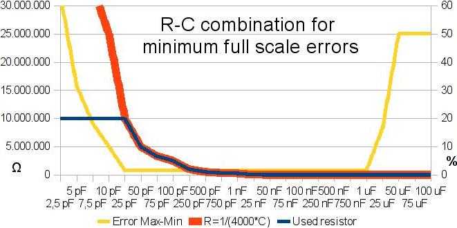
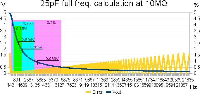
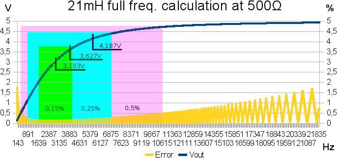
Basically when using this detailed resistor ladder accurate measuring reactance can be done with only two frequencies.
In main measurement range there is frequency around 1.1 kHz for capacitors and 2.3 kHz for inductance – frequency are for targeted point of half input voltage.
Higher frequencies are needed only for measure lower ranges; for inductors less than 30mH to increase reactance and in capacitors less than 15pF for decrease reactance.
Lower frequency is needed for higher values; more of 700H in inductance to decrease and above 1uF for increase reactance in capacitor.

This also adds to justification of usage 16 resistors for digital potentiometer, especially if experimental PC version shows that square wave AC is far worst for measure than sine.
PWM module can generate almost sine wave in this small frequency range.

4. Power supply from battery – in this case parallel PC port
With all above I practically have finish setup for analog part of my PC/LCR tweezers device.
As I mention already I plan to use 3.3V power supply.
Source in PC version would be 5V from LPT port output pins, and in tweezers from dual NiMH 2.4V/300mA batteries (4.8V).
For stable 3.3V regulator I plan to use S-1132B33 LDO Regulator with shutdown pin.
For PC version I also need voltage level translator to enable normal communication between 5V LPT port and 3.3V MCU.

17
Other (Public) / Re: Low cost tweezers type LCR meter
« on: October 30, 2011, 10:47:51 AM »
After doing some research and simulations, here is update by key points:

1. Cheap digitally controllable frequency generator in range of 100 Hz up to 2 MHz
After some research and thinking I decide to use clock pulse (square wave) from microcontroller as AC signal, generated by PWM module.
Using DDS is too expensive. Replacement can be made by using monolithic function generator like XR-2206.
Of course controlling frequency can be difficult.
By using 8 or more analog switches + shift register with different resistors at each output and joined at pin 7 or 8 of XR2206 in parallel, it is possible to get frequency control to some degree.
How detail it would be, depends on resistors in parallel combination.
Generated signal will have unknown frequency, so it must be measured at microcontroller, which bring additional complication.

When it comes to basic, it is totally irrelevant what type of signal is used. Wave type is only important for calculating exact values for DUT.
So by using square wave instead sine wave, I will need to calculate several first odd harmonics to get enough precise value of DUT.
That calculation is performed only once at end of all measurements, so it’s not time critical.

2. Digitally fast selectable resistance for range.
In this segment I did some extensive simulations.
After looking schematics of classical DMM and thinking, I decide to go with resistor in parallel combination rather than series.
Here is some schematic and links that I find useful:

First thing I was doing are simulations to see what resistors I need for selection.
I used at first standard set of 6 resistors; 100, 1k, 10k, 100k, 1M and 10M ohms.
However there was a problem, microcontroller can provide current of max 20mA, which means that I can’t use 100 ohm resistor.
First closest resistor for 5V supply with safe side of about 15mA is 330 ohms.

With this basic resistor set in place there is mater of frequency.
And after some thinking I decide not to make experimental version on microcontroller, but on PC similar to ZRLC meter.
With this I will have far better experiment environment to test different frequencies and wave shapes.
After I finish PC version I’ll have completed half of LCR meter, because PC with soundcard replaces only microcontroller and display.

So for simulating I use frequencies from 100 Hz to 22050 Hz, which classical 16bit soundcard can generate.
DUT detection is made by applying at lowest resistance low and hi frequency.
If voltage is identical on both readings and it is 0 or Vin, then test is repeated using highest resistance with low and hi frequency.
First reading non 0/Vin and closest to half of Vin is used to decide what type of DUT is.
According to that, it is calculated guessed value for DUT.

Here I got problem, I need to choose resistor and frequency to be the best for accurate measurement.
At first tests I use loop and go thru available resistors calculating frequency for each one and using only one with highest frequency.
This method produced strange readings with error difference of few percent at two closes DUT values.
After that I was made full frequency analysis to see what is going on.
Here is a result for capacitor calculations:

Blue line shows used resistors which have at least error difference (yellow line) in full frequency (100-22050Hz) scale.
Simply put if this resistor is used with any frequency it will produce lowest calculation errors than any other.
For analysis to get best accuracy I was using only resistors with error difference below 2% and in that region I see that graph is hyperbola.
After calculations I came to this formula:
Rmeasure=1/(4000*Cguessed)

So with this formula I can from guessed capacitor get the best resistor for measure (red line).
After that, there was left a problem to get right frequency in combination with that resistor to obtain the best measurement.
Then I was made another calculations with this result:

This graph shows full frequency calculations for 25pF capacitor with 10Mohms resistor.
Calculations for other capacitors are also done with similar results.
As you can see, error (yellow line) between real value and simulated reading do not pass 2% for entire frequency range.
To get the best frequency for testing we must target midpoint at certain frequency band.
Using filter for 0.5%, 0.25% and 0.15% errors I get frequency band in which is best to perform measurements.
Guessed capacitor is in most cases off the real value, so using bigger band of frequencies is logical choice, however by already selecting right resistor we done that.

So now it is only left to target more precise region, and using band with 0.15% error give us at midpoint 2.506V.
This is actually recommended value – half of Vin (5V in my case) for measurement in voltage divider setup.
After recalculations I get next formula for determining optimal frequency:
fmeasure= sqrt(3)/(2*pi*Cguessed*Rmeasure)

I was done similar simulation-calculations for inductors.
When it comes to selecting right resistor, result was identical as in capacitors, I only got inverted hyperbola.
So formula is slightly different:
Rmeasure= 25000*Lguessed

But when determining right frequency there I got much different results:

As you can see, frequency band for 0.15% error have midpoint at 3.103V.
This is not like capacitor and further tests + simulations confirmed that this is better than 2.5V.
So formula for getting right measuring frequency of inductor is:
fmeasure=Rmeasure/(2*pi*Lguessed*sqrt(1.613))

On end I made simulations for resistors, but I was using DC voltage of 5V, not AC signal.
I use this to eliminate possible inductance and capacitance of resistor – DUT.
If I want to know what inductance or capacitance resistor have, I can manually set measurement for it.

Note for graph; I used resistors in exponential increased value, so error regions and midpoint don’t match visually.
Used resistors are in this increment: ...98, 99, 100, 110, 120...
But as you can see in lowest error region I got midpoint at 2.475V which I rounded to 2.5V, because this is more convenient.
So formula for selecting right resistor is:
Rmeasure=Rguessed

After I performed these analyses and take simulations, I got far better results than with previous test methods:
Capacitor
RangeResolutionError
1pF-1nF1pF0.130%
1nF-1uF1nF0.130%
1-10uF15nF0.137%
10uF-100uF1uF0.83%
100uF-1mF10uF9.64%
1mF-2mF500uF23.35%
Inductor
RangeResolutionError
1uH1uH100.00%
2-10uH1uH22.39%
10-20uH1uH7.47%
20-30uH1uH4.78%
30-50uH1uH2.98%
50-100uH1uH2.19%
100-200uH1uH1.06%
200-500uH1uH0.52%
500uH-1mH1.5uH0.22%
1mH-1H1mH0.13%
1H-1kH1H0.13%
1-50kH250H0.52%
50-100kH1kH1.29%
100-200kH15kH5.55%
Resistor
RangeResolutionError
0.1Ω0.2Ω100.00%
0.2-1Ω0.2Ω61.29%
1-3Ω0.2Ω8.16%
3-10Ω0.2Ω4.19%
10-30Ω0.2Ω1.34%
30-100Ω0.3Ω0.55%
100-300Ω0.6Ω0.27%
300Ω-1kΩ0.21%
1-3kΩ0.26%
3-10kΩ20Ω0.35%
10-30kΩ80Ω0.26%
30-100kΩ260Ω0.33%
100-300kΩ780Ω0.26%
300kΩ-1MΩ3kΩ0.42%
1-3MΩ7.6kΩ0.25%
3-10MΩ20kΩ0.35%
10-30MΩ76kΩ0.25%
30-100MΩ580kΩ0.53%
100-300MΩ4.6MΩ1.37%
Values below 200uH and 10pF can be far more accurate by using frequency of 1 or 2MHz.
Resistors below 30 ohms will remain inaccurate because I can’t use resistor lower than 330 ohms.
However I considering using 3V supply which will enable me to go low as 200 ohms, but for this I need to do more simulation and testing.

Off course this is all done in simulator with ideal DUT, and I place limit of 10bit ADC readout.
So actual testing/measuring will be worst, because of noise and other electrical leakage.
With all of this I got required range, but I was not happy with resolution.
Solution is to add more resistors and use analog switches to combine them in parallel to get far better range and thus better resolution.

3. Accurate measuring AC voltage with ADC.
For this last point I found that precision full-wave-rectifier (precise op-amp AC to DC converter) will be best for ADC. Here are some links for that:

So to continue work on my LCR tweezers, I decide to start with PC.
With PC I can generate from soundcard precise frequency, which can be sufficient to measure almost all DUT values of required range.
In this version I will construct and test analog part of LCR tweezers:
  • SMD probe
  • Protection from charged capacitors
  • Digitally selected wide range of resistors
    • Digital selector (shift register, microprocessor?)
    • Analog switchers or Reed relays?
    • Chosen set of resistors for optimal resistor range
  • Power supply from battery – in this case parallel PC port
  • Software for selecting and working with analog part
  • Optimized programming for detecting and calculating DUT

After this, I’ll have more than half job done.
Only thing what will be left to do are integration of precise full-wave rectifier, microprocessor and display.

18
Other (Public) / Low cost tweezers type LCR meter
« on: October 18, 2011, 06:43:02 PM »
I started new project; LCR tweezers - impedance measuring instrument, capable of measuring resistance, capacitance or inductance.
One of main reasons is lack of cheap instruments of this type on market.
Other one is that I have pile of SMD components that need testing and sorting out.

My other projects are currently in hibernation, mainly because they started to be too complex for my taste in current state of development.
In battery capacitance tester I replace 8bit ADC0804 with more precise and cheaper ICL7135 which also increase number of ICs for interfacing with parallel port.
At that point I was seriously thinking to use microcontroller with 10 or 12bit ADC, and replace entire circuit.
On pulse charger after numerous experiments I find out that complex charging signal is more effective, especially if contains complex charging/discharging sequences.
But to experiment with that I need to build far more complex hardware with standard ICs, at which point I decide to start working with microcontrollers.

My pile of SMD components is nightmare to sort out with standard multimeter. I have ability to measure capacitance, inductance and resistance on it, but switching between ranges to find out what is component value started to be never ending painfully slow process.
So I start to look for small tweezers type multimeters which can detect and measure components of inductance, capacitance and resistance. Sadly, existing ones are too expensive for my taste as amateur in electronics.
But this gave me idea to determine what exactly I need. Here is specification of tweezers which I want to construct:
  • Low cost – less than 30 euros.
  • Portable and small size, to easily fit into hand as tweezers.
  • Battery powered for easy handling – idle auto power off (bonus for integrated charger).
  • Based on KISS principle – fewer components as possible (single chip with few passive parts would be ideal).
  • DUT (Device Under Test) automatic type detection – L, C or R (bonus for diodes, etc.)
  • Fast type detection – under 1 second.
  • Fast measurement – under 1 second.
  • Low accuracy – 20% or better.
  • Wide measurement range if feasible:
    • Inductance – 1 uH to 1 H
    • Capacitance – 1 pF to 1 mF
    • Resistance 1 ohm to 10 Mohm
As you can see, I need small, cheap and simple sorting tool. I already have other instruments if I want more precisely testing/measuring.
After searching net I find this as possible project which may have something that fit/closely match or can be adapted to my specification:

I. group: Exact or closely matched
There are projects which involve measuring all three components.
They are based on measuring phase shift between voltage and current.
One is Russian version of LCR meter; you can find details at http://kripton2035.free.fr/lcr-repository.html or http://www.pro-radio.ru/measure/6873/ (Russian language).
Other one is at http://www.circuitcellar.com/microchip2007/winners/third.html

Now, these hardware projects are complex, expensive and big. Adopting them to my requirements is not feasible (my estimation).

II. group: Closely matched and can be adapted
Other instruments are mostly based to test LC, RC or only one L/C/R type and do not measure by default all three types.
There are many working principles from measuring charging time to change of frequency.
Here are some of those projects:
Adaptation any of this to my needs will require adding additional switching, some independent test hardware and then some way to determining what DUT it is.
However I find one version closest to my needs at http://members.cox.net/berniekm/super.html there is also changed version at http://benryves.com/journal/3632205

This is simple, small and it can be made to measure all three types.
However measured range is limited and some measurements require up to few seconds or are unreliable, like inductance where entire device can hang and need resetting.

I can recombine these schematics by using more LC components for resonance to increase measurement range and resistors to achieve my specifications.
For switching it will be needed to replace relays with MOSFETs or analog switchers like CD4066.
And all of that must be built with SMD components to be small.
In short: feasible but I put this solution for last resort if all other possibilities are exhausted.

III. group: Create completely new device from available methods
On end I decide to build my own microcontroller based LCR meter using new methods with new approach.
After thinking I came to conclusion that first thing to do is to find a way to determine what type of DUT is.
So I need something what all three types have in common and the answer is resistance.
Not standard DC resistance, but AC resistance or impedance - reactance.

Simply put I need to measure impedance at two or more different frequencies.
If DUT maintain identical reactance on all frequencies, then DUT is resistor and measured reactance value is actually resistance.
On other hand if DUT reactance becomes higher at higher frequencies then it is inductor.
To find out inductance, we can use formula to calculate it:


And at last if DUT reactance becomes smaller at higher frequencies then it is capacitor.
To calculate capacitance from reactance we can use this formula:


So this is simple method to automatically detect what type of DUT it is and do measurement.
Now all that I have to do is construct impedance meter, which actually work similar as classical DC ohmmeter with addition of using AC with changing frequency and made calculations for capacitance and inductance from measured reactance.

Searching web for this type of instrument did yield some results.
There is solution based on the same method but using computer soundcard and PC software – ZRLC meter.
See details at http://www.sillanumsoft.org/ZRLC.htm
This software solution is nice and it’s worth using it, but it is not mobile and has limited measurement range because it uses max 40 kHz from soundcard with single resistor.
By my calculations for my range I’ll need selectable resistance and frequencies up to few MHz.
Nevertheless this is proof that this method works. Here is another example for this method:

Surprisingly I didn’t find any other complete projects which will be using solution like this.
All other projects are about special functions like ESR etc.
However I find some other useful information:

So that is idea, now I have to do more detailed research, crunch some data and make calculations to find out how to build it.
Guessing these would be primary key points:
  • Cheap digitally controllable frequency generator in range of 100 Hz up to 2 MHz
  • Digitally fast selectable resistance for range
  • Accurate measuring AC voltage with ADC

19
Programs / Oron Helper - Greasemonkey script
« on: September 11, 2011, 01:37:32 PM »
I didn’t find useful existing helper scripts for Oron, like ones for RapidShare or MegaUpload.
So I wrote my own.
You can download it from here: oron_helper.user.js
or from: http://userscripts.org/scripts/show/112760
http://userscripts-mirror.org/scripts/show/112760

Script does next stuff:
  • Automatically click on Free download button (can be disabled in script options).
  • Removes download delay.
  • Automatically reload page after waiting time for next download elapsed.
  • Showing countdown of waiting time in title (can be disabled in script options).
  • Alerts you when captcha is ready (can be disabled in script options).
  • Automatically starts to download (can be disabled in script options).
For changing script options, you must edit script.

20
LARP (Public) / Re: Popis velikih LARP dogadanja 2011
« on: July 18, 2011, 08:40:26 PM »
Obavijest za sve one koji imaju novac na Rajskim Vrhovima:

Zbog interesa i razvoja situacije ingame odluceno je da ce se pustiti odredena kolicina novca van za upotrebu na drugim dogadanjima.
Serije novca su:
  • crno-sive boje
  • u apoenima od 1 i 2 vepra
  • datuma 21-24.07.2011
  • priznati ce se na svim dogadanjima Rajskih Vrhova
Svi igraci koji imaju i zele preuzeti novac za svog karaktera mogu sukladno pravilima novca za Rajske Vrhove ih preuzeti u utorak 19.7.2011 (vjerojatno i ostale utorke)  u Tomislavcu izmedu 20 i 22 sata.
Ako niste u mogucnosti u ovom terminu preuzeti novac, slobodno me kontaktirajte ili nekoga od organizatora sa Rajskih Vrhova.

21
LARP (Public) / Popis velikih LARP dogadanja 2011
« on: June 20, 2011, 12:07:52 AM »
Evo kratki popis velikih LARP dogadanja:

Fantasy LARP:
21-23.6.2011 Rajski Vrhovi XIV
lokacija: Zumberak, vise...
21-24.7.2011 Jaska 8
lokcija: kraj Jastrebarskog, vise..
13-15.8.2011 Rajski Vrhovi XV
lokacija: Zumberak
26-28.8.2011 Majcin Gaj
lokacija: kraj Vrbovca

FALLOUT LARP:
Event je trenutno odgoden do daljnjega.

Za ostale detalje pogedajte na larphr webu.

22
Transformer calculator (Public) / TO DO list
« on: May 09, 2011, 12:23:50 AM »
This is additional TO DO list for future upgrade of Transformer program.
However, for making any update I’ll need data about any transformer coils and formulas.
So if anyone is willing to help, I appreciate it.

  • field for selecting the core shape (toroid, U, E, I, W)
  • the input Amps should be user defined;
  • wire thicknes in P1 should be user defined + a field with optimum calculated for both P1 and S1 (maybe S2) wire thickness;
  • if it is feasible, due to the S1 wire thickness (in the stepdown type) to put an area cross section field (maybe different shapes for the wire);
  • possibility of using transformer taps on S1 to regulate the output voltage
News 26.Jan 2013
  • simplify user input fields and program handling
  • improve corrections on core/wire specification
  • add option to calculate with unknown core/ferrite by inputting few simple measurements
  • calculate bare essential data to match wide range of cores/materials – if you need more precise or detailed calculation, then you need professional program or manual calculations

23
Other (Public) / Re: Pulse charger...
« on: March 27, 2011, 03:46:19 PM »
There is error in previous schematic; MOSFET must be P-type to work properly.
I was originally made on test board with P-type and it didn’t work as expected, probably because used MOSFET was too weak.
After that I rearrange parts and made N-type version which worked. Here is modified version:


In here capacitor C8 was placed to reduce load on MOSFET and add better spike output.
When used without C9 it produces 3-4 spikes in short duration and acts like desulfator.
C9 was closed loop with primary coil and significantly increase power output.
Charging in this configuration is much faster, but output spikes are reduced to about 50V.
Running frequency is set to 6.4kHz.


Here is shown coil with only primary (upper left) and prototype device with completed coil.
There is 766 turns in both coils, primary one uses copper wire of 1.4mm diameter, and secondary of 0.6mm.
Inductance in primary is 0.994mH, resistance 0.99 ohm, in secondary is 1.89mH with resistance of 6.22 ohms.
As you can see this coil is big, 500mm in length and 43mm in diameter, but it does job done. :)

However I was not happy with this, because I want bigger pulses and smaller charger, so I started from beginning with new direction.
After searching thru other project with pulsed chargers I find these two most interesting:
http://www.freepatentsonline.com/5633574.html
http://www.wipo.int/pctdb/en/wo.jsp?WO=2003088447

And so I create list of what my charger must have:
  • Go on directly at AC line
  • Generating short high voltage spikes (100V+)
  • Pulses must be strong to do actual charging not only desulfation
  • Made in KISS principle
  • Smaller dimensions
So after thinking I decide to try with something like this:


This schematic should fulfill all listed must haves.
CD4060 with potentiometer will provide frequency range from 760Hz to 3.5kHz.
Switch provides selection of duty cycle from 50%, 25%, 12.5%, 6.25%, 3.125% and 1.5625%.
IC3 with two transistors make driver for MOSFET.
Entire device get current from AC line thru C2/D1-2 and power for spikes goes form rectified power AC line.
This should provide powerful and stable 250-300V spikes.

Anyway this is idea, after testing and building prototype I’ll post results.
WARNING: Do not attempt to do this at home, this uses live AC current and it can easily kill you!
Remember, I’m trained amateur and I know what I’m doing. ;)

24
Other (Public) / Re: Pulse charger...
« on: March 11, 2011, 08:36:10 PM »
Here is update on restoring sealed battery; in short I gave up.
After breaking seal and examining internal plate status, there was no point in repair attempt.
There was crystal structure which deformed and at multiply points shortened opposite plates.
So even if I remove that crystal form, there is question; will I have enough plate material to be able to restore it in normal working condition?
I’m thinking at best to quarter capacity, but amount of work and price of chemicals equals more expensive than new one.

One another observation; while performing tests with measuring internal resistance I found that my method form Wikipedia isn’t good.
So I have to find something else for reliably test internal resistance of battery.

Next, about tests with charger, my initial setting was excellent for small batteries up to 2Ah, in range from 1.2V to 24V.
There is only need to adjust DC output voltage with duty cycle.
My first test was on 70Ah battery and after 2 days of charging voltage raises to 12.4V, so I decide to do testing on smaller battery to see result more quickly.

Next test was done on 4.5Ah battery, and after 4 hours I didn’t notice significant improvements.
Charger consumption with battery was 0.38A and I need to get more power to charge it faster.


This is new setting; on left are out pulses with only light bulb connected.
In middle are pulses for MOSFET gate and on right you can see brightness of light bulb at this setting.
Frequency is 1.2 kHz, with 65% duty cycle on, voltage output 10.6V/23.9V (DC/AC scale at multimeter), consumes 0.29A with only light bulb and 1.12A when charging battery.
With this I was able to fully charge 4.5Ah battery in about 3:30 hours.
Coil was very hot, so I rearrange ventilator from blowing out of casing to in at coil to make it more temperature stable.

Then I calculate that for charging 70Ah battery I’ll need more than two continuous days, which is too long.
So I decide to push charger to limit (and beyond).


This is more powerful setting; 1.6 kHz, 75% duty cycle on, voltage output 12.8V/28.9V (DC/AC scale), it consumes 0.34A with only light and 2.2A with battery.
On bottom left picture are out pulses when battery is charging.
As you can see HV spike is completely absorbed and charging is done only 23% in cycles during coil discharge.
Notice on bottom right how 24V light bulb is now much brighter.
At this point I was not sure if ventilator can keep coil cooled enough. Anyway I decide to push forward and see what happens.


This is end result (I remove pieces of melted plastic casing to get better picture of PCB).
In about 6 hours of charging, coil is gradually heating plastic casing and ventilator to a point of melting.
Ventilator at this point becomes working slower allowing coil to become hotter.
After that, everything gone in runaway effect, ventilator casing was deformed and stops working.
Third of casing was melted away and nearby screw fell on PCB making short connection in which MOSFET blocks in on state and starts heating until breakdown occurs.

So for more powerful version I need to make some heavy duty coil.
However I also need more current at output for faster charging.
There is also problem of HV spikes if there is no load present.
Therefore I think to make new approach, something like this:


This will solve HV spikes problem in primary side by capturing it in capacitor.
Frequency must be tuned in capacitor - coil resonation, therefore each new pulse will go with capacitor discharge and reduce collisions/current waste.
Transformer model will produce more current at output for faster charging and hopefully solve problem if no load is connected (yeah I know this won’t work, let me dream a little bit ;)).

25
Other (Public) / Re: Battery capacitance tester...
« on: March 11, 2011, 02:53:54 PM »
After intense testing I wasn’t happy with some results and decide to do some changes/upgrades to tester.


Here is new improved schematic.
  • Voltage reading at and beyond 15V shows some nonlinearity, probably because leakage current through 6.2V Zener diode.
    So I remove it and place regular diode to VCC for input overvoltage protection. Input impedance of ADC0804 is 5k (as is stated in datasheet), so I reduced input voltage divider to 19k.
    Now at 15V consumes about 0.23mA, but reading is more accurate. I also have to change base voltage in program from 8.925 to 8.88V.
  • There was some significant difference in voltage at halogen lamp and battery terminals.
    I was hoping this won’t affect calculation, but it does. So I add sense wire which is connected at clamp as +12V wire and all voltage reading are now done at battery terminals.
  • I originally placed halogen bulb inside casing, but that will melt casing if left too long working. There is also problem of changing bulb. So I add PTR connector and mount halogen bulb in it.


Here is how prototype now looks like.

However I’m thinking to add resistor + OP amp for current measure up to 2.5A at halogen load.
To switch between voltage and amperage I’m planning to use MOSFET transistors.
This would eliminate calculation of how much halogen light bulb consumes (which only gives estimate value) and add options to easy replace it with more powerful version.

26
Other (Public) / Re: Pulse charger...
« on: March 01, 2011, 05:06:00 PM »
I made some modification to original schematics.
After testing I decide to remove two driver transistors, because 555 IC have enough pull-up to GND for driving MOSFET alone. However I placed 1uF capacitor to stabilize raise-fall gate voltage.
I was also experimenting with different frequencies and came to conclusion that original setting of about 600Hz is optimal. Higher frequencies have lover voltage peak and I need pulses beyond 100V for battery sulfation problem. So to work with higher frequencies I need high voltage transformer (better solution) or coil with lower inductance - higher consumption (worst solution).


Here is new schematic. I place small incandescent light bulb as control and ballast at output. Without load, coil transfer all HV spikes to MOSFET which can burn out in short time. I also added small ventilator to cool down coil.


Here is prototype board and test casing for it.
Frequency is set up to 600Hz, out voltage on DC scale is 5.8V and 12.7V at AC scale of multimeter. Power consumption of electronics (without coil/MOSFET/ventilator) is about 40mA, and without ventilator it consumes 200mA. Ventilator is from old TNT graphic card and consumes 90mA at 12V.

In theory this charger should never overcharge battery and can be place forever to charge battery (something like trickle charger). But those theories I’m planning to test.
My sealed battery during testing didn’t show any changes. I have recorded internal resistance of battery. In entire time it didn’t change at all, it’s constantly about 257 kohms (yes, kilo ohms).
For measuring (calculating) I use method from Wikipedia:
http://en.wikipedia.org/wiki/Internal_resistance
There are also other methods, like:
http://www.buchmann.ca/Chap9-page2.asp
http://madsci.org/posts/archives/2003-11/1067871870.Ph.r.html

Conclusion is; my sealed lead battery is sulfated beyond repair with charge or/and have some structural damage... My plan now is to open it and try with magnesium sulfate to restore it back to life. If someone interested how, here some links:
http://www.ehow.com/how_5152330_fix-dead-motorcycle-battery.html
http://ysuusy.com/Lead_Acid_Car_Battery_Repair.html

I’ll test my charger with other batteries, and I’ll report back how things going... :)

27
Other (Public) / Pulse charger...
« on: February 21, 2011, 12:34:15 AM »
I decide to start new project, pulse charger...
In my last project with battery capacitance tester I stuck with trying to recover battery by draining it to 8V and recharging in several cycles.
This however didn't produce any result and I have feeling that my old charger is not suitable in recovering process.
This 30 years old charger have transformer with 4 power diodes for rectifier and small light bulb for control...
So I decide to build add-on for this charger to transform it into pulse charger.

After searching web for some useful schematic, I found only these sites:
http://electronics-lab.com/projects/power/008/index.html
http://www.freewebs.com/acselectronics/batterypulser.html
http://www3.telus.net/sail/sj23/e_electrical_tips/e04.html
http://sites.google.com/site/johnbediniresearcharchive/radiant-100

None of this fits my needs, so I decide to build my own version based on John Bedini principle.
I use 555 timer, set it up for frequency range from 500Hz to 3kHz, then with two out transistors set driver for MOSFET IRF640.
Then I test how this works with different coils and at end I find that 6mH toroid choke coil is optimal for this configuration.
I didn't want to use my test coil so I made one using parts from dead PC ATX power supply.


Here you can see on left desoldered coil, in middle core without wires (inner diameter is 13.5mm, outer 23.5mm and width 9.7mm).
On right picture is my new coil of 6mH, to make it I use wire with diameter of 0.3mm (with insulation) and 8.5m long.
I use instrument to measure inductance, but I think there are 294 turns unless I miscount somewhere. :)


Here is schematic for prototype. I used small light bulb (24V, 4W) as battery for calibrating device. Input voltage from my test transformer is 20V so I need to add resistor R5 of 47 ohm to drop down voltage to about 17V before 12V regulator to avoid heating.
R3 is for adjusting frequency form 500Hz to 3kHz and R8 for length of positive out pulse (duty cycle).

For testing device I decide to use another dead battery, it is 12V sealed lead battery with 7.2 Ah from 1993. It is originally used 5 years in UPS and then collected dust without charging. Using classical charger I fill it up under minute and drain less than 30 seconds to 2V.

Initial test charging with pulse charger is set as 1.4kHz, 60% duty cycle and last about 21 hours. After resting it holds voltage of 2.9V, and connecting 24V/4W light bulb will drop voltage to 0.2-0.3V. During this test charging, MOSFET become hot and there was no progress on battery, so I decide to reduce duty cycle below 50%.
After calibrating again with 24V light bulb I got this:


On left side is signal which produce 555 IC and it reaches 6V with 46% duty cycle. In center image is signal which drive MOSFET, for start it uses +2.4V and after -1.4V to block gate (without MOSFET out is +/- 4V). On right picture you can see out spike, it reaches 200+V and quick drops to 0V (under 46% of duty cycle). With this I solve heating MOSFET, and now only coil become warm.

During calibrating device to 700Hz I found that light bulb becomes bright, even brighter than connected directly to 20V. So I measure current and I detected some interesting phenomena. This 24V light bulb, directly on 20V, drains 3.6A current, but when connected to charger it drains only 230mA. Less than 15 times!
I think I should do another project involving DC pulse currents and regular light bulb of 100W. I'll try to use current directly from mains power to se if I can get same brightness on 100W bulb and to consume only 10W... :)

28
Alternative / Tehnika Eckasha Maharic Pečata(Croatian language only!)
« on: February 13, 2011, 05:24:55 PM »
Tehnika Eckasha Maharic Pečata *
Napredni glavni princip za osobno i planetarno liječenje

Kratki uvod

Učenja Azurite Melchizedek Cloister Emerald Reda svi su temeljeni na Zakonu JEDNOG koji prepoznaje povezanost i međuzavisnost svih dimenzija "stvarnosti" i priznaje da živući Bog ili Duh je živ u svim stvarima. Sva učenja Azurite Melchizedek Cloister Emerald Reda su vrhunska i posebnog priznanja znanstvene i energetske osnove Zakona Jednog. Praktična svrha ovih učenja je da doista oslobodi i osnaži sve, kroz proširenje svijesti i obrazovanog prosvjetljenja, kroz koje poštovanje, ljubav i kooperativno stvaranje je njegovano unutar globalne zajednice. Te perspektive potpuno obuhvaćaju geofizičko planetarno iscjeljivanje kao unutarnja posljedica osobnog usklađivanja i proširenja.

Tehnika Maharic pečata je glavni alat od iznimne važnosti tako da je učinjen besplatno dostupan svima. Kao sve Azurite MCEO tehnike i alati, Maharic pečat je čvrsto utemeljen u Univerzalnu Objedinjenu fiziku Polja, drevna Merkaba mehanika i znanost o Predlošku Materije (tzv. Božanski Nacrt). Ove tehnike su poznate kao Tehnologije Bio-Regenesisa koje su nekada bile opće znanje, učene u pradrevnim školama Uznesenja kod napredne Ljudske kulture, i smatrane kao standard, ali i kao glavna stvar, u dnevnoj praksi.

Maharic pečat, poput svih Bio-Regenesis Tehnologia, podrazumijeva konkretnu primjenu kod energije svjesnosti usmjerene na, i unutar, srži manifestacije predloška tijela. Ova tehnika izravno aktivira specifične matematičko-geometrijske odnose unutar i između Anđeoskog Čovjeka i planeta, organskog, evolucijskog nacrta, koristeći pre-materijske hidro-plazmičke frekvencije 10., 11. i 12. Dimenzije Mahara Struje.

Maharic Struja je bila u potpunosti ponovno usidrena na ovom planetu po prvi put u više od 210 tisuća godina, na GRU-AL točke, Sarasota SAD-u, Signet 2 od Planetarne Templar Mreže, na dan 1. siječnja 2000. Tijekom prvih 12 mjeseci, nakon tog vremena, blijedo Srebrna 6-kračna Zvijezda ili Hierophant je korišten u vježbama Maharic Pečata. Ovaj simbol predstavlja elektro-tonski program za 11. i 12. Dimenzionalni aspekt Univerzalne Kathara Mreže. Kada smo koristiti taj Hierophant Simbol u vježbama Maharic Pečata, pokrenuli smo aktiviranje uspavane 11. i 12. frekvencije unutar Zemlje i našeg vlastitog bio-polja. Kada smo izazvali aktivaciju ovih frekvencija, možemo započeti proces ponovnog postavljanja Izvornog Božanskog Nacrta unutar cijele naše energetske strukture, DNA predložak i fizičko tijelo. Struja Maharic je također jako važan val nosilac svih simbola i tonova koji se koriste u svim kasnijim vježbama.

Kako je sve više i više ljudi radilo s Hierophant i Maharic Pečatom tijekom 2000 godine, povećao se 11. i 12. dimenzionalan frekvencijski kapacitet Zemlje i ljudi. To nam je omogućilo da koristimo u vježbi sve više i više složene oblike 6-kračnog Hierophant simbola. Na primjer, umjesto vizualizacije 6-kračne zvijezde, mi smo vizualizirati 12- kračnu zvijezdu. Kao posljedica toga, donijeli smo sve više i više Maharic struje u naša bio-polja, a zatim smo bili u mogućnosti koristiti sliku 24- kračne zvijezde, pa 48-kračne zvijezde, te čak i 144-kračne zvijezde. To je pak pokrenulo sve više i više razine aktiviranja Maharic struje unutar planete i našeg vlastitog bio-polja. Zatim, tijekom druge važne prilike u 2001, Indigo djeca i ljudi pomogli su usidriti sljedeću razinu frekvencije zvanu Eckasha u energetsko bio-polje planete.

ECKASHA MAHARIC PEČAT

Eckasha se još naziva Eckasha Božje Sjeme i nosi matematičku frekvenciju koja odgovara temeljnim strukturama ključnih aspekata našeg Univerzalnog sustava koji se zove Ecka i Eckasha Svemiri. (Više informacija za te razine našeg prostranog Svemira mogu se naći u knjizi Voyagers II, 'Dance For' serije radionica i znanosti duhovnosti i stvaranja - Seattle 03). Ovaj lijepi simbol sadrži dodatno vrlo složene i moćne Božje Svjetovne frekvencije, osim frekvencija 6-kračnog blijedo Srebrnog Hierophanta.

Kada po prvi put radite Eckasha Maharic Pečat, nije neobično da imate poteškoća vizualiziranja boja i simbola unutar Eckasha, tako da se često početno vizualizira kao ravna 2-dimenzionalna crno-bijela slika. Kako postajete navikli na simbol i vježbe, možete uvidjeti da se povećava vaša sposobnost da ga zamislite kao više-dimenzionalnog i obojenog simbola. Ako imate poteškoća vizualizacije ikakvih simbola u bilo kojoj od tih tehnika, jednostavno IMAJTE NA UMU da je simbol tamo. Jednako vrijedno iskustvo vizualizacije je poznato kao "vidjeti-osjetiti", gdje se mogu "vidjeti" svaki detalji, a ipak ne "vidjeti" išta, u uobičajenom smislu riječi, gdje znate što vidite čak i ako ne "vidite" to! Ljudi koji imaju tendenciju da iskuse više od osjećajne razine (osjetilno učenje), a ne vizualno ili slušno, vrlo često funkcioniraju na ovoj razini vidjeti-osjetiti ili čak "čuti-osjećati". U tom kontekstu, vizualizacija je srodna mašti, i jednako je vrijedan i snažan način iskusiti bilo koju tehniku predstavljene u KS.

Nakon sidrenja i aktivacije ovog Eckasha simbola, količina frekvencije koju je planet akumulirao (uvukao u svoje bio-polje) uvelike se povećala. Kao posljedica toga, frekvencijska sposobnost vezivanja kod ljudi se također povećala. U vidu ovog uzbudljivog razvoja, bilo tko sada može početi ove tehnike pomoću Eckasha simbola umjesto 6-kračne blijedo Srebrne Zvijezde ili Hierophanta u vježbama Maharic Pečata. Izvorna Dugačka Verzija Maharic Pečata koristeći 6-kračne (ili više kračne) Hierophanta, se još uvijek može koristiti kao početni korak prije Eckasha simbola, ako to želite.

Uz redovitu uporabu MAHARIC pečata ili
ECKASHA MAHARIC pečata ćete:

  • Započeti proces aktiviranja 8. do 12. čakre osobne Kathara Mreže.
  • Pomoći otvaranju Kristalnih Pečata u tijelu (koje inače blokiraju DNK aktivaciju).
  • Otvoriti Planetarno sučelje Bio-Napajanja unutar svog osobnog tijela, omogućujući tijelu kao vozilu da postane doista učinkovit alat za trajnu planetarnu mrežu i sveto mjesto rada.
  • Izazvati aktivaciju DNK predloška koji će postupno i automatski aktivirati punu 12 dimenzionalnu Merkaba.
  • Omogućiti voditeljima ozdravljenja da prenose 12D frekvencijske pod-harmonike, pružajući snažnije, dugotrajno, često trajno, olakšano iscjeljivanje - oslobođeno od deformacija osobnog i klijentskog energetskog polja.
  • Zaštiti korisnike od neharmoničnih energija povezanih s Liječenjem, Astralnih i Sanjajućih Vremena projekcija, te drugim potencijalnim izvorima zadiranja / infiltracije polja.
  • Pomoći svadljivoj "Indigo Tip 3" djeci (davati preko roditelja).
  • Pojačati rezultate svih duhovno usmjerenih aktivnosti.
  • Uskladiti osobne energije i energije okoliša.
  • Napraviti Morfogenetski ponovni uzorak, očistili Karmičke / Miasmik Otiske, koji bi inače blokirali aktivaciju DNK predloška i postizanje istinske ekspanzije svijesti i potpuno utjelovljenje Kristovih Principa.
  • Uskladiti, revitalizirati i obnoviti sve aspekte fizičkog i Suptilno-Energetskog Sustava Tijela.
  • Pripremiti i opremiti sudionike da primaju i drže sve veći protok viših frekvencija energija, koje teku u Planetarnu mrežu i osobne morfogenetska polja koje proizlaze iz intenziviranja Zvjezdanog Aktivacijskog Ciklusa, koji je sada u tijeku (2000-2017).

Kada redovito trenirate Eckasha Maharic Pečat, opskrba visokih frekvencijskih energija koje se mogu privući u naša bio-polja iz Planetarnog Maharic Štita je ograničeno samo vlastitim energetskim kapacitetom. Naš kapacitet frekvencije se može postupno povećavati s dosljednom primjenom Eckasha Maharic pečata, kao i drugih preporučenih Keylontic znanstvenih tehnologija.

Tehnika
ECKASHA MAHARIC PEČATA

Ovo je kako Eckasha Kôd izgleda, a krugovi u sredini su Reuche.
Prije uporabe: Čitajte kroz korake i prakticirajte vizualizaciju, te se polako upoznajte sa njihovim redoslijedom.
  • Zamislite 2-dimenzionalnu sliku "Eckasha Simbol Kôda", kao da je slika nacrtana na crnoj pozadini unutar vašeg čela. Eckasha je Simbol Završnog Kamena ili Kôda Božjeg Sjemena za Vremensku Matricu. Njegove boje obilježavaju frekvencijski spektar od Triadic, Polaric i Eckatic razina Energetske Matrice i 15 frekvencijskih Dimenzija. On će se koristiti kao ključni kôd za otključavanje 12. dimenzijskog Maharic Štita u osobnoj i planetarnoj skalarnoj mreži.
  • UDAHNITE, dok vizualizirate Eckasha simbol u središtu mozga u epifizi.
  • IZDAHNITE, koristeći izdahnuti dah da čvrsto premjestite Eckasha dolje, kroz Središnju Vertikalnu Tjelesnu Struju (energetsku struju u središtu tijela), van između nogu i ravno dolje u Zemljinu jezgru (13. Čakru).
  • UDAHNITE, dok zamišljate da možete vidjeti na Zemljinoj jezgri ogroman, Diskovni oblik Kristalne Platforme od Blijedo Srebrnog Svijetla, koja se proteže prema van na horizontalnoj ravnini kroz cijelo tijelo Zemlje van u atmosferu. Vizualizirajte Eckasha kako lebdi u središtu diska (ova slika predstavlja Planetarni Maharic Štit, skalarno-valna mreža sastavljena od frekvencije dimenzija 10/11/12, s Eckasha pozicioniranim za aktiviranje Planetarnog Štita.)
  • IZDAHNITE, dok gurate svoj dah van u Zemljin Maharic Štit, zamišljajući u toku izdisaja da sila daha počinje rotirati Zemljin Maharic Štit.
  • UDAHNITE, koristeći dah za privući Blijedo Srebrno svjetlo od Zemljinog rotirajućeg Maharic Štita u Eckasha, pozicioniran u središtu Planetarnog Štita.
  • IZDAHNITE, koristeći izdahnuti dah za guranje Blijedo Srebrnog svjetla kroz cijeli Eckasha, tvoreći Eckasha sjajnijim i pulsirajućim s Blijedo Srebrnim svjetlom.
  • UDAHNITE, zamislite da sjajni Eckasha trenutno bljeska Tamno Crveno i onda se vrati na normalu, zatim koristite dah da privučete Eckasha okomito gore iz svog položaja u Zemljinoj jezgri, na poziciju 30 cm ispod nogu (pozicija vaše uspavane osobne skalarno-valne mreže Maharic Štita). Dok udišete Eckasha gore od Zemljine jezgre, Zamislite da ostavlja za sobom debeli kabel Blijedo Srebrne Svijetlosti, jedan kraj Srebrnog Kabla ostaje priključen na Zemljinu jezgru, a drugi na Eckasha (kabel predstavlja Liniju Napajanja Energijom, preko koje ćete povući energiju gore od Zemljinog Maharic Štita u svoj osobni Maharic Štit)
  • IZDAHNITE s osvrtom na pozicioniran Eckasha 30 cm ispod nogu i koristite izdahnuti dah da gurnete rasprskavajući Blijedo Srebrno Svijetlo van na horizontalnu ravninu od Eckasha. Zamislite oblik Diska, Kristalne Platforme Blijedo Srebrne Svijetlosti, oko 1.2 metara u promjeru, koja se proteže na horizontalnoj ravnini 30 cm ispod nogu, okolo Eckasha u sredini. (Ova slika predstavlja vaš osobni Maharic štit.)
  • UDAHNITE, dok koristite dah da privučete više Blijedo Srebrne Svijetlosti gore kroz Blijedo Srebrni Kabel od Zemljine Jezgre u Eckasha, u središtu vašeg osobnog Maharic štita.
  • IZDAHNITE, koristeći dah da gurnete Blijedo Srebrno Svijetlo iz Eckasha van u svoj Maharic štit. Zamislite da vaš Maharic štit sada pulsira kako se ispunjava Blijedo Srebrnom Svjetlošću iz Zemljine jezgre.
  • UDAHNITE, ponovo povucite još Blijedo Srebrne Svijetlosti gore iz Zemljine Jezgre kroz Blijedo Srebrni Kabel u Eckasha i zamislite kako se Blijedo Srebrni Kabel širi na 1.2 metara širine, formirajući stup Blijedo Srebrnog Svijetla koji ide iz Zemljine Jezgre izravno u vaš Maharic Štit promjera 1.2 metara.
  • IZDAHNITE, ponovno koristeći izdahnuti dah da gurnete Blijedo Srebrno Svijetlo iz Eckasha van u svoj Maharic Štit, dok zamišljate da vaš Maharic Štit "poprima vlastiti život". Disk se iznenada "preklapa prema gore" sa "pucajućim" osjećajem u obliku STUPA promjera 1.2 metra Blijedo Srebrnog Svijetla okolo i prolazi kroz vaše tijelo (to je Vaš Maharic PEČAT. privremeni skalarno-valni stup za frekvencije svjetlosti dimenzija 10/11/12 ~ to blokira neharmonične frekvencije od dimenzija 1 do 12 i počinje usklađivati neharmonične frekvencije u vašem tijelu i bio-polju na njihove izvorne iz savršenog prirodnog poredka)
  • UDAHNITE, zamišljajući da dah povlači Blijedo Srebrno svjetlo iz Stupa koji obuhvaća tijelo U svaku tjelesnu ćeliju; osjetite žmarce kako se Blijedo Srebrno Svijetlo kreće kroz fizičko tijelo.
  • IZDAHNITE, zamišljajući da možete osjetiti energiju Blijedo Srebrne Svijetlosti kako se širi U svaku pukotinu tijela, a zatim van oko tijela u Bio-polje.
  • Dišite normalno kroz minutu - dvije, dok se osjećaj Blijedo Srebrne svjetlosti kreće kroz vas, kako bi osjetili prisutnost energije Blijedo Srebrnog Stupa Maharic Štita 1.2 metra oko vašeg tijela. Što više vremena trošite dišući i osjećajući energije, više frekvencija dimenzija 10/11/12 privlačite u svoj Stup, što će povećati duljinu vremena koliko će Stup Maharic Pečata ostati u vašem bio-polju.
  • Vratite vašu pozornost na Eckasha još uvijek postavljen 30 cm ispod vaših nogu.
  • UDAHNITE, koristeći dah za povući Eckasha gore kroz Središnju Vertikalnu Tjelesnu Struju na vrh vaše glave (7. "Krunska" Čakra), do točke oko 90 cm iznad glave (14. Čakre).
  • IZDAHNITE SNAŽNO, koristeći dah da brzo proširite Eckasha van na horizontalnu ravninu od 14. čakre, dok Eckasha iznenada ne "nestane" iz pogleda, s blagim "pucajućim" osjećajem.
  • Dišite normalno, dok za trenutak vizualizirate briljantan 1.2 metara Blijedo Srebrni Stup Svjetlosti koji se proteže iz Zemljine jezgre prema gore, u potpunosti obuhvaćajući vaše tijelo i proteže se daleko iznad glave u Zemljinu atmosferu, te u jednu Zvijezdu Blijedo Plave Svijetlosti daleko u dubokom svemiru. Vaš Maharic Štit je sada privremeno aktiviran i vaš Stup Maharic Pečata se privremeno očituje unutar vašeg Bio-Polja. Maharic Pečat će u početku ostati u vašem Bio-Polju između 20 minuta do 1 sata. Što se više ova vježba koristi, Stup će ostajati dulje.
  • Za brzo pojačanje Eckasha Maharic Pečata, jednom kada je cijeli proces bio izveden unutar 24 sata: Jednostavno Zamislite iskru Blijedo Srebrnog Svjetla na epifizi, te izdahnite brzo dolje u Zemljinu Jezgru i zamislite da se Zemljin Maharic Štit vrti, pozovite u misli Blijedo Srebrni Kabel i Udahnite sve do gore oko vas kabel promjera od 1.2 metara, formirajte Stup i produžite ga "u duboki svemir" do Zvijezde Blijedo Plavog Svijetla.

Copyright © 2010 A & A Deane, Sva prava pridržana;
Dio MCEO serije Slobode Učenja®

* Nije namijenjeno za Dijagnosticiranje, Tretiranje, ili Liječenje zaraza ili bolesti, niti je za prikazivanje ili njihovo tumačenje, na bilo koji način, kao zamjena za profesionalnu medicinsku, kiruršku ili psihijatrijsku skrb ili liječenje.

29
Alternative / Moji prijevodi...(Croatian language only!)
« on: February 13, 2011, 05:02:17 PM »
Evo u kratko da navedem stranice sa kojih prevodim određene stvari tako da možete vidjeti originale.

Slijedeće navedene stvari su dostupne sa Azurite Press stranica.

30
Other (Public) / Re: Battery capacitance tester...
« on: February 09, 2011, 09:54:41 PM »
Finally after awhile I finished prototype. I did some changes in schematic due incorrect readings under load.
I reduce number of resistors at zener bridge and now measuring consumes about 0.21mA. On top of that I did some corrections in program, because voltage drop from first zener (9.1V) diode is now 8.925V under input of 15.3V. Error in reading is +/- 0.025V, and in worst case scenario can be max 0.05V.


Here is new schematic and device prototype.


When I was charging battery for first time in awhile, it reaches 15.8V and after 30-40 seconds slowly drops to 13.4V. In first (top) graph you can see second charging after discharge. It begins at 13.85V, then drops to 18.3V after 3-4 seconds and continues to charge normally. Still don't know why this happens during first few charging cycles.

On second graph is shown several discharges thru 5W halogen lamp. Here you can see that all are more or less identical. One interesting thing is steep voltage drop after 12.1V to 10.2V. Normal batteries don't have that voltage drop.
On top of all that, as you can see, for charging this battery it takes only 22 seconds, and to discharge it thru 5W halogen about 80 seconds.
So I still can figure it out if battery is really dead or not. This 70Ah battery was before using desulfator usually charged for about 3 hours. I'm going to try few times to drain it with 50W halogen lamp down to 8V and recharge it. Then I'll know for sure if it’s really dead or not... ;)

Pages: 1 [2] 3