Assembling
ICT device
Testing
Program
 
IC Tester HELP - Assembling section
Assembling IC Tester device

IC Tester is electronic device for testing ICs (integrated circuits) and may test some others electronic elements with appropriate addon.
Device is connecting to parallel (printer) port at computer, currently you can connect it to PC and Amiga computers.

On IC Tester device you can test ICs with up to 16 pins.
Assembling costs is very low, parts for device costs about 20 dollars, for other elements, that depends how skilful you are, minimum 5 dollars.
Here are instructions for assembling IC Tester device, to be precise IC Tester 2 device.
If you build/have IC Tester device, you can use upgrade information to upgrade existing IC Tester to IC Tester 2. You can find in ICT upgrade assembling section all instructions for that upgrade.
IC Tester 2, like upgrade, has only small changes and none of them are critical, so you can use any program version on new IC Tester device.

All phases of construction and testing will be described in steps.

Step 1:
Getting parts what we need for build device, on table below are all listed:
Part No Part Type Amount required
IC1SN 741501
IC2-5CD 40944
IC678051
T1-34BC 547 (or similar)34
T35BC 558 (or similar)1
D1, D41N41482
D2-31N40022
LED1Green, 3 mm1
LED2, LED4-5Yellow, 3 mm3
LED3Red, 3 mm1
R1-31 kOhm3
R6-85,6 kOhm3
R10-41, R46-47100 Ohm34
R4275 kOhm1
R43560 kOhm1
R44-45470 kOhm2
C1330 uF/10V (microF)1
C2-3470 uF/25V (microF)2
C4-5100 nF2
CONN1DB 15 female, right angle1
CONN23,5 mm stereo headphone jack1
CONN33 pin male single line connector1
SOC1DIL 16 pin socket (long pins)1
OtherDIL 16 pin socket4
OtherDIL 24 pin socket1
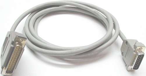
Parts for data cable
OtherDB 15 male connector1
Other12-15 wire regular cable1-2 meters
OtherDB 25 male connector1
Parts for power
Other3,5 mm stereo headphone connector1
Other3 wire regular cable1-2 meters
OptionalTransformer 2x6V/5VA1
Optional2-3 wire regular power cable1-2 meters
OptionalFast fuse 500mA1
Optional9V power connector1

Information about printed board you can find in PDF document
SOC1 is test socket and you can use standard DIL 16 pin (with long pins if available) or 16 pin TEXTOOL socket, but be aware that TEXTOOL socket cost equally as entire listed components.
D2 and D3 are 1N4002 but you may use 1N4007 or similar diode.
For C1 you may use any capacitor from 220 to 470 uF (micro Farad) of 10 Volts or higher voltage, but watch for size of it.

Something about price, by my estimation all listed parts in table should cost about 25 dollars.
In that price isn't included price of printed board and optional parts, in most cases you probably make this board by yourself.
In that case you should spend about 5 dollars, otherwise you can spend up to 30 dollars.

When you manually making board, in PDF document are printed board layouts, when printing check that Fit to page option isn't checked to get ratio 1:1. If you need change something on board, use PCB file with appropriate free software to modify it. See download section.
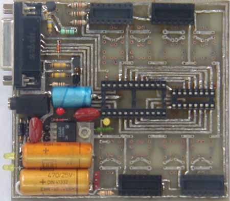
Dimension of board is 100 by 93 millimeters, +/- 1 millimeter variation isn't catastrophic important is that holes for IC1 to IC6 match.
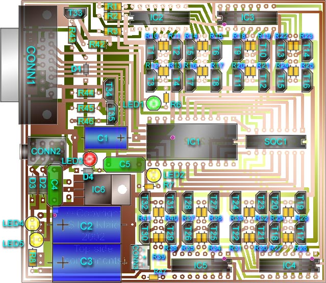
On picture below is IC Tester 2 schematic (click on image to enlarge):

IC Tester 2 schematic
Step 2:
After you get or create printed board, next is soldering elements on it...
On picture below is silkscreen layer with position of elements on board.

Positions of electronic elements

Now here is suggested soldering guide:
  1. If you have copper film in holes you can skip this and next step. For easier soldering, put solder on copper at edge of all holes in top copper side of board, don't close hole.
  2. Solder with pieces of wire 5 holes which connect top and bottom side of board. Holes are marked with violet points on silkscreen layer.
  3. Now solder CONN1 connector to board, on top and bottom side. Yes I know it's not easy, use thin electric iron head.
  4. Solder sockets by this order: IC1 socket, SOC1, IC2 socket, IC3 socket, IC4 socket and IC5 socket.
  5. Solder next parts by this order: R1, R2, R3, T33, R43, R42, D1, T34, R44, T35, R45, R46, C1, CONN2, LED3, C5, D4, LED2, R7, IC6, C4, D2, D3, C2, C3, CONN3, R47, LED4, LED5 and R8.
    Half soldered board

  6. Now solder transistors and resistors T1 to T32 and R10 to R41 as pairs in this order:
    T1, T3, R10 and R12 as first pair and R11, R13, T2 and T4 as second pair, etc.
  7. Finally solder LED1 and R6.
Step 3:
That's it for device, next we need to make data cable.

Exact wires positions on cable

In picture above are exact wires positions on data cable. Soldering points in picture are set to match ones on DB connectors.
If you use cable with more than 12 wires, extra wires solder to pins with black line on it (for DB 25 pins: 18-21; DB 15 pins: 2, 9-11).

Data cable
Step 4:
In the end, we need to create power supply for device.
Basically you can power device from 9V battery, or from transformer. For that you need to create 3,5 mm stereo connector which is connected to 9V power connector or transformer, details are described under Assembling IC Tester upgrade in Step 6.
Here on picture below is schematic for constructing power supply using transformer.

Transformer schematic

Power cable of 2-3 wires you can soldered on transformer and on fuse, another end of fuse solder to rest point of transformer. Transformer output of dual 6V or higher up to 12V (note higher voltage make IC6 to heat more) solder to 3 wire cable with 3,5 mm stereo headphone connector at appropriate places.
O.K. we soldered all, now go to Test IC Tester device section and read how to test newly created device and cable.
© Copyright Silvio Klaic
Linux | Vim | HTML 4.01