
Assembling |
Testing |
ICT device |
Program |
Here are instructions for testing IC Tester device and cable.

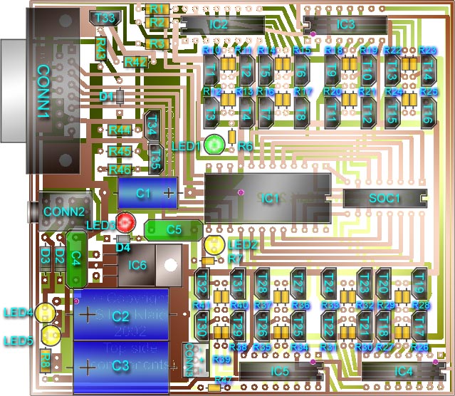
On picture above is silkscreen layer with position of elements on board.
You can help with it in next testing, with brown color is marked copper lines
which are on top side (components side) and with green color copper lines from
bottom side.
After soldering, we need to check if everything is properly soldered.
For that purpose, remove all ICs from sockets, then you'll need multimeter or
something else to test if wire or copper line on board is whole or it's broke.
We don't need perform full check right now, only basic will do, follow this
steps:
O.K. That's it. Now we finish basic testing at device and cable.
Detach cable from device and place ICs at their sockets.
Now start ictester program with option -t, eq: ictester -t
and follow instructions.
If there's still error then something is wrong with port, try to use another port.
If there's still error then recheck integrity of all copper lines at IC Tester on CONN1.
When you connected power, LED2, LED4 and LED 5 (yellow led diodes) will light up.
Now you can press enter key and do test. If error occur, it will be one of those:If there's still error then, if you fix the problem, send me email and wrote
what was the problem and how you fix it.
You can not fix the problem? No, that's not the option, FIX IT!!!![]()
You will need piece of wire for this test.
If there's still error then problem could be in cable or in IC1, recheck again if they working properly.
If there's still error recheck if IC2, IC3, IC4 and IC5 working properly.
If there's still error recheck if IC2, IC3, IC4 and IC5 working properly.
If there's still error, it's possible that input data are corrupted, recheck cable and try to close all programs that may use this port.