Assembling
Testing
OCR addon
Program
 
IC Tester HELP - Testing section
Testing Diode/OCR addon device

Here are instructions for testing Diode/OCR addon device and cable.
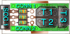
Positions of electronic elements on OCR addon

On picture above is silkscreen layer with position of elements on board.
After soldering, we need to check if everything is properly soldered. Now start ictester program with option -to, e.q.: ictester -to and follow instructions. Here are in details explained all phases of that testing:

  1. Quick test - Perform quick test on IC-Tester device
    • Remove from test socket any IC, addon or other part that may be in it
    Now with this test program do quick check on IC Tester device to see if necessary parts working fine and if it's possible to do test on Diode/OCR addon device.
    Now you can press enter key and do test. If error occur, it will be one of those :
    • Test fail, not found respond from device.
      Respond from device not detected or not powered - low battery, follow next steps:
      • check if you are properly connected power to ictester device
      • check if any power coming to ictester device
      • check if input power is 6V or up to 12V, possible low battery?
      • do full test on IC-Tester device with -t option
    • ERROR: got data from test socket at ictester device and there shouldn't be any!
      It's possible that some element is in test socket or some IC at IC Tester device is damaged, follow next steps :
      • check that nothing is on test socket and run test again
      • do full test on IC-Tester device with -t option
    • Test fail, got data from test socket at device and there shouldn't be any!
      Here is also possible that there is some element in test socket or problem is with components on IC Tester device, follow next steps:
      • check leads on ictester board which connects IC1 socket and SOC1 if they are correctly soldered
      • check if is IC1 socket correctly soldered and IC1 correctly connected
      • check if all copper leads to CONN1 are properly soldered
  2. Add-on test - Make full test on OCR/Diode add-on
    • Connect OCR/Diode add-on on test socket
    • Remove from add-on test socket any component that may be in it
    Here is perform full test of Diode/OCR device, press enter key to begin test. IF error occur, it will be one of those :
    • Test fail, got data on other pins.
      It's possible that some copper lines are soldered together, to solve problem follow next steps:
      • check copper lines on pins 1 and 2 and at end of R3 and R2 possible contact
      • check copper lines on end of R3 and pin 3 possible contact
      • check copper lines on end of R3 and pin 4 possible contact
      • check copper lines on end of R3 and pins 5 and 6 possible contact
      • check if transistor T3 working correctly, it may burn out
    • Test fail, got data on other pins.
      This is identical error as last but for other part of addon device, to solve problem follow next steps:
      • check copper lines on pins 2 and 3 and at end of R2 and R1 possible contact
      • check copper lines on end of R2 and pins 5, 6, 10 and 11 possible contact
      • check copper lines on end of R2 and pins 7 and 9 possible contact
      • check if transistor T2 working correctly, it may burn out
    • Test fail, got data on other pins.
      To solve problem follow next steps:
      • check copper lines on end of R1 and pins 13, 14, 15 and 16 possible contact
      • check copper lines on end of R1 and pins 11 and 12 possible contact
      • check if transistor T1 working correctly, it may burn out
    • Test fail, transistor T3 not respond correctly.
      Problems with transistor T3, to solve problem follow next steps:
      • check if resistor R3 working correctly, it may be burn out
      • check if transistor T3 working correctly, it may be melted (short circuit)
      • check if transistor T3 working correctly, it may burn out or it's misplaced
    • Test fail, transistor T2 not respond correctly.
      Problems with transistor T2, to solve problem follow next steps:
      • check if resistor R2 working correctly, it may be burn out
      • check if transistor T2 working correctly, it may burn out or it's misplaced
      • check if transistor T2 working correctly, it may be melted (short circuit)
    • Test fail, transistor T1 not respond correctly.
      Problems with transistor T1, to solve problem follow next steps:
      • check if resistor R1 working correctly, it may be burn out
      • check if transistor T1 working correctly, it may burn out or it's misplaced
      • check if transistor T1 working correctly, it may be melted (short circuit)
    Basically last three errors may repeat but with different suggestions about solving the problems. This test can more accurate report problems with addon device than test for IC Tester device, so follow suggestion and you should fix problems fast.
    After all tests pass O.K. you may now use addon device for testing diodes or OCR elements, see Program - ictester section for more details.
© Copyright Silvio Klaic
Linux | Vim | HTML 4.01